Release notes
In staying true to our vision to create the world's most user-friendly and powerful turbomachinery design platform, we are constantly improving and enhancing our software:
CFturbo 2023 R2
November 2023
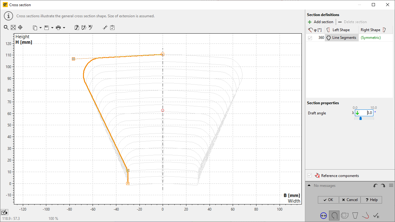
Draft angle for spiral sections
Upper sides of the cross-sections are not necessarily tangential at the center line, but can have a draft angle with respect to the horizontal direction.
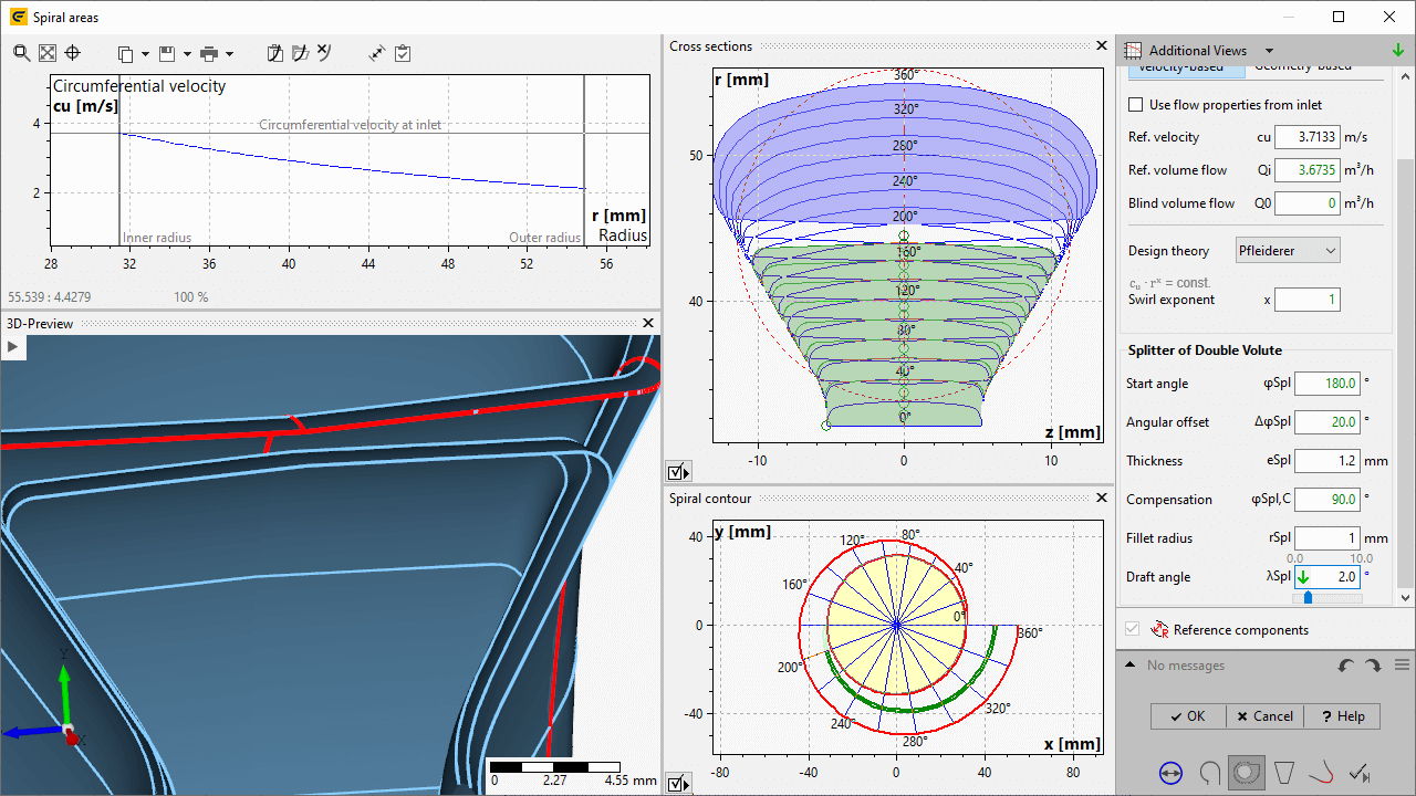
Draft angle for splitter of double volutes
Splitter can have a draft angle with respect to the horizontal direction optionally on upper and lower side.
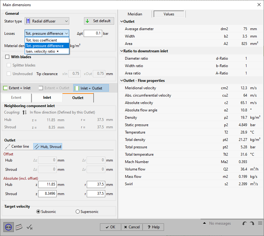
Specification of stator losses
Stator losses can be specified by loss coefficients ζ or total pressure loss Δpt . For compressible fluids the isentropic velocity ratio can be used alternatively.
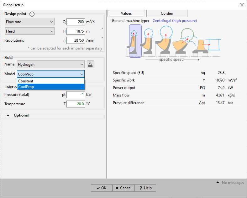
Variable density for liquids
For compressible liquids, CoolProp can be used for the calculation of pressure dependent density.
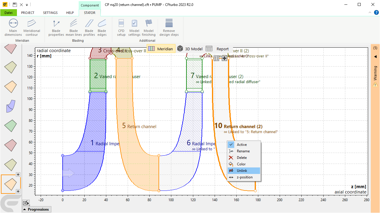
Duplicate with linking to master component
Duplicated linked components remain identical even after modification of the master component.
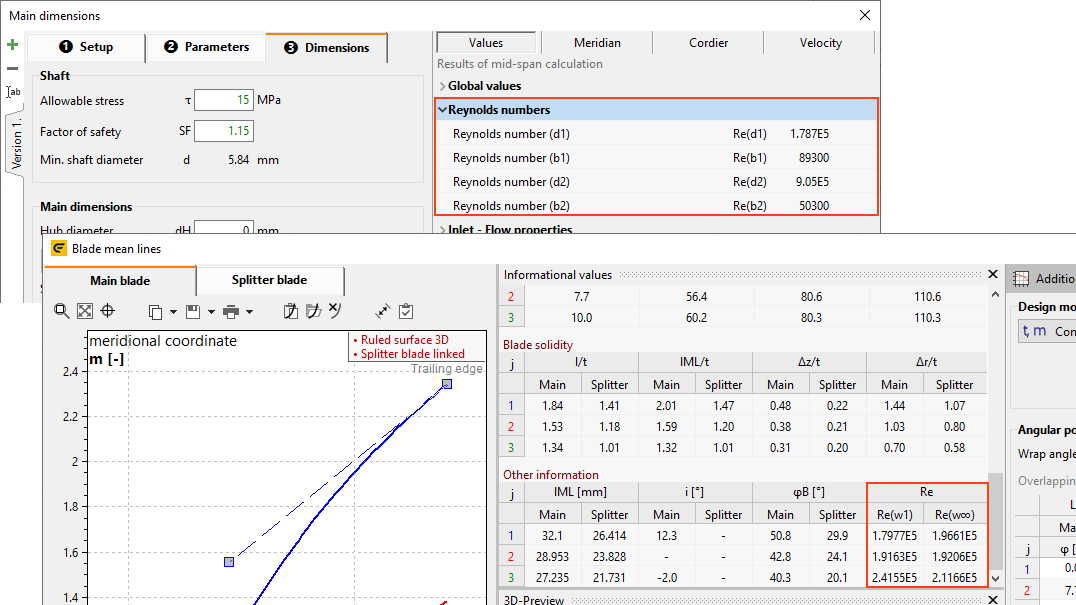
Display of Reynolds numbers by different definitions
Display in the Main dimensions and Meanline design steps using different velocities and diameters, based on publications e.g. by Casey/ Robinson.
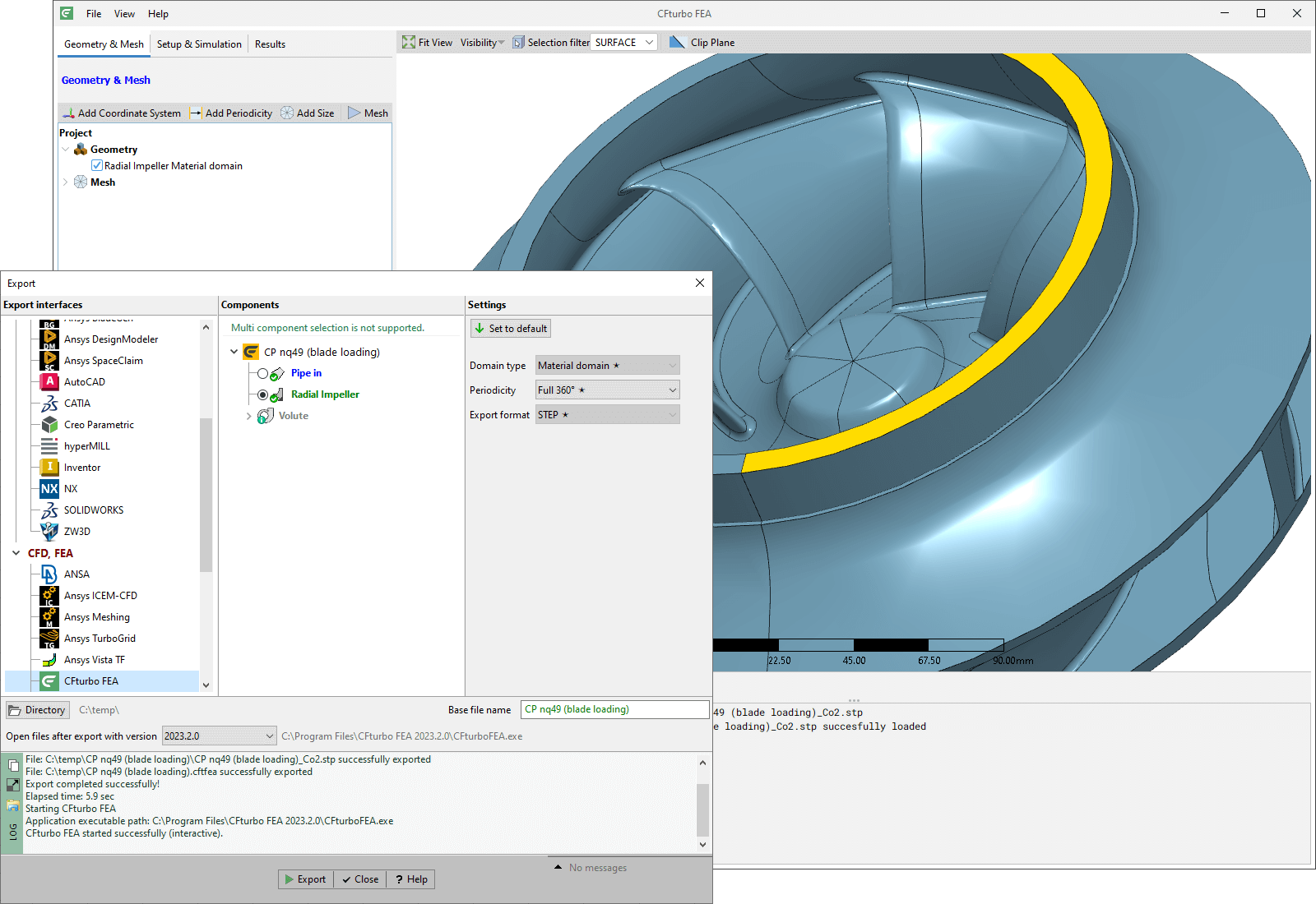
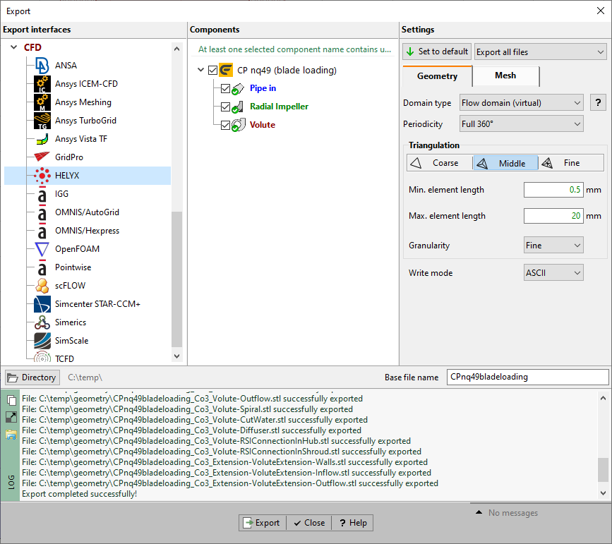
Export interface to HELYX
Interface to CFD software HELYX from the company ENGYS.
https://engys.com/products/helyx
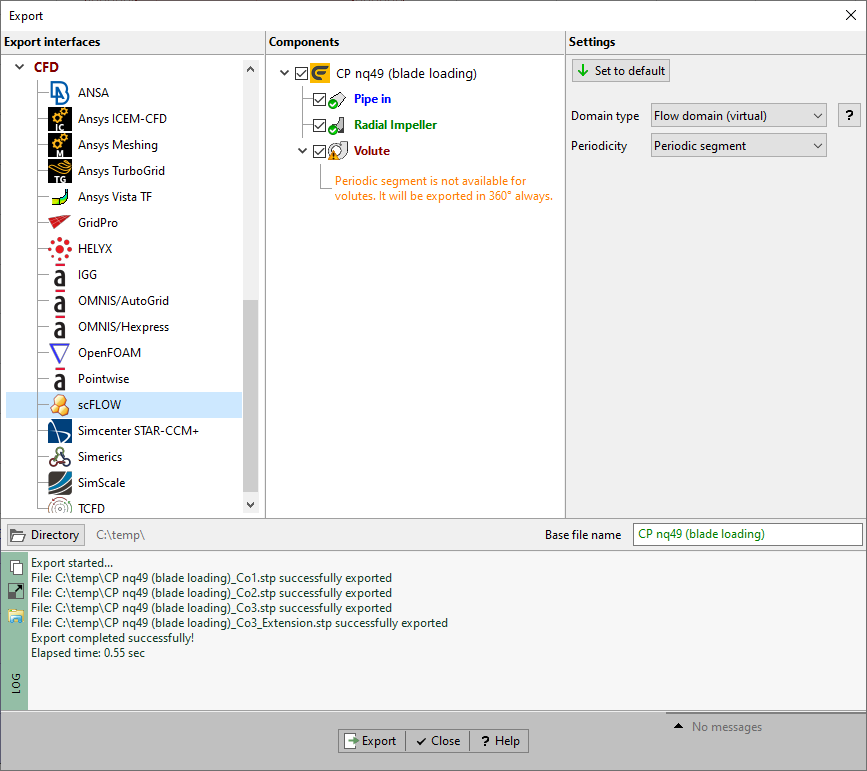
Export interface to scFLOW
Interface to CFD software scFLOW from the company HEXAGON.
https://hexagon.com/products/cradle-cfd-scflow
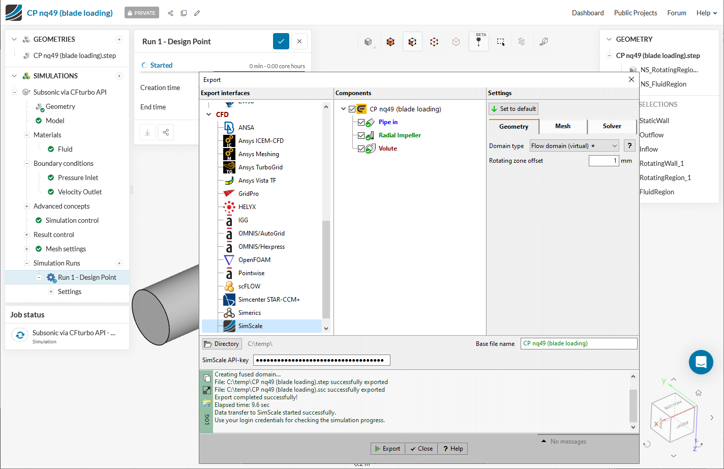
Automatic SimScale start
Exported files are transfered to SimScale, SimScale is opened in the browser and the project is loaded.
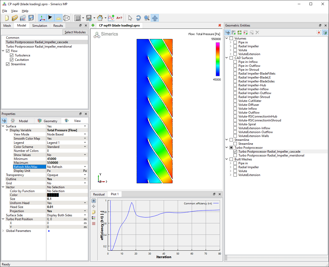
Direct support of Simerics TurboPost
CFturbo export to Simerics now contains pre-configured support of the TurboPost module.
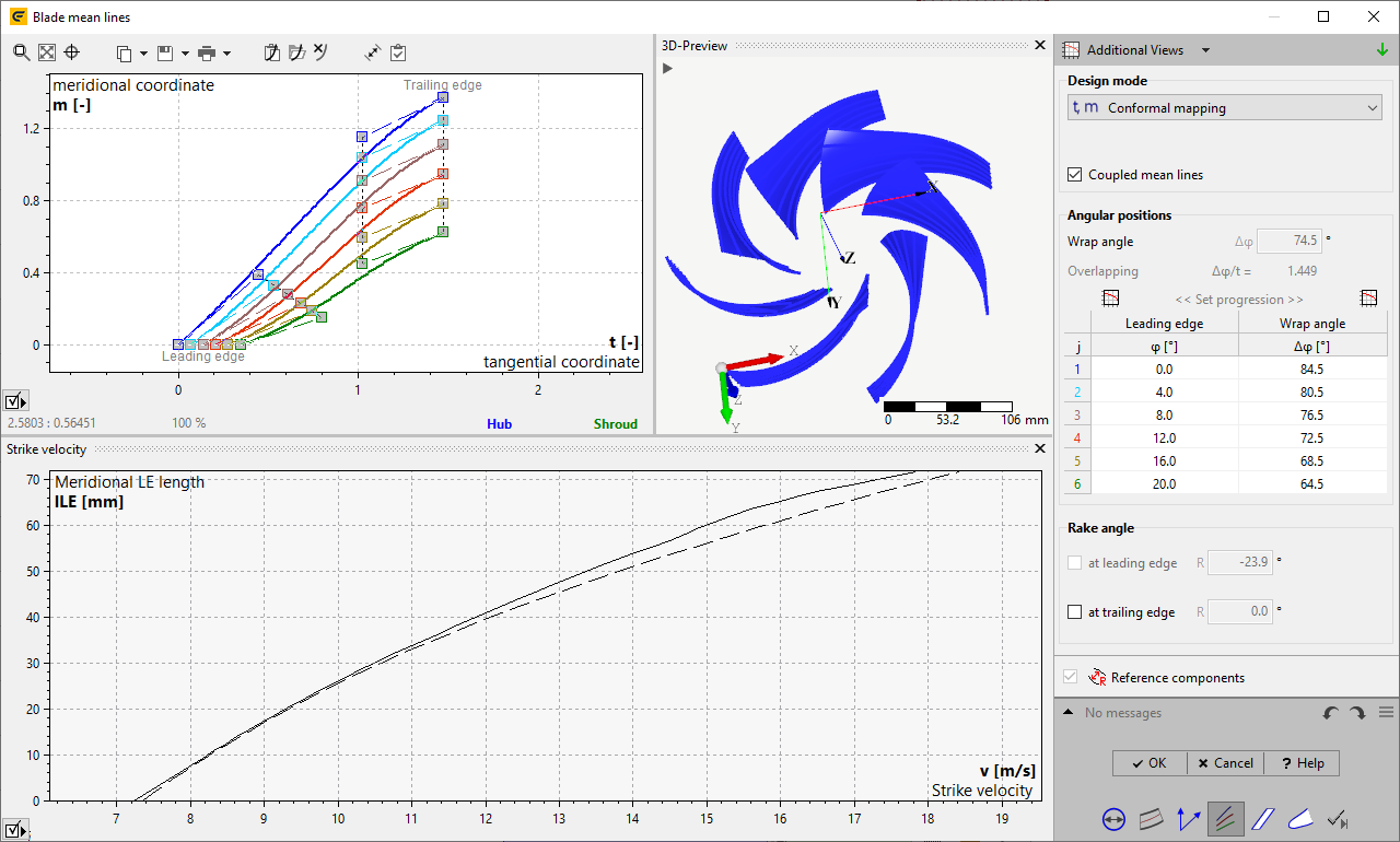
Strike velocity at blade leading edge
Strike velocity is important for pumps for the evaluation of fish friendliness.
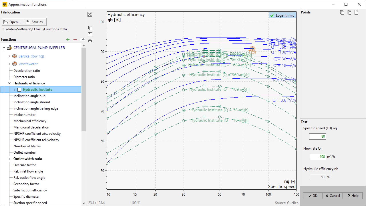
Update of efficiency curves from Hydraulic Institute (HI) for pumps
Curves are now based on the latest publication "Hydraulic Institute Program guideline for Rotodynamic Pump Efficiency Prediction", HI 20.3-2020.
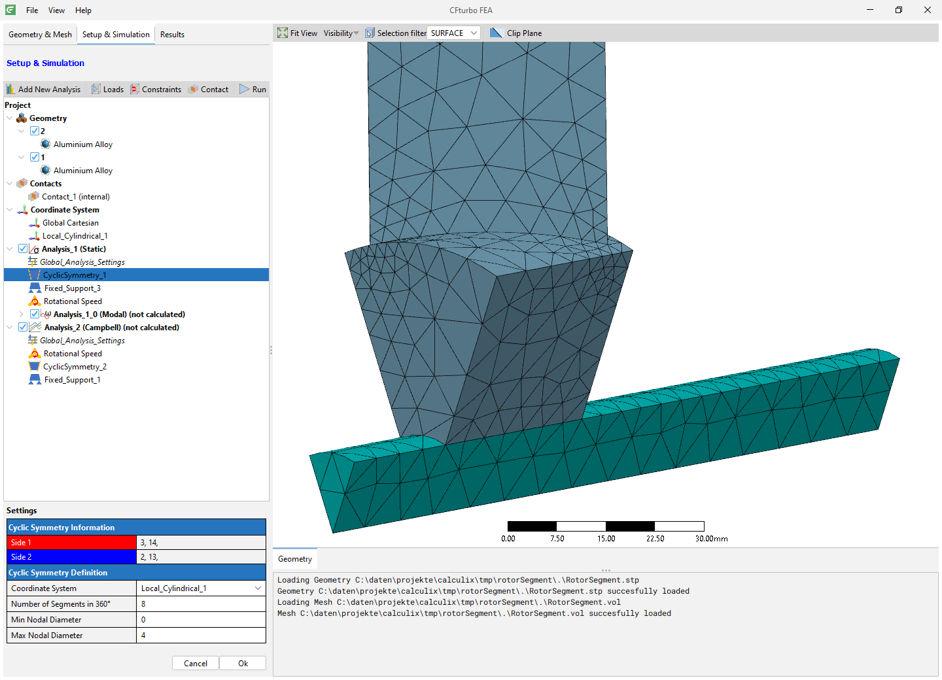
CFturbo FEA: Specification of periodic symmetry
For rotational symmetric geometry, it is sufficient to consider only a single segment, which enables faster simulation times.
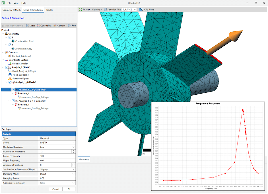
CFturbo FEA: Harmonic Response Analysis
Harmonic response analysis has been added as a further type of analysis and can be used to determine the structural response to a periodic load.
CFturbo 2023 R1
May 2023
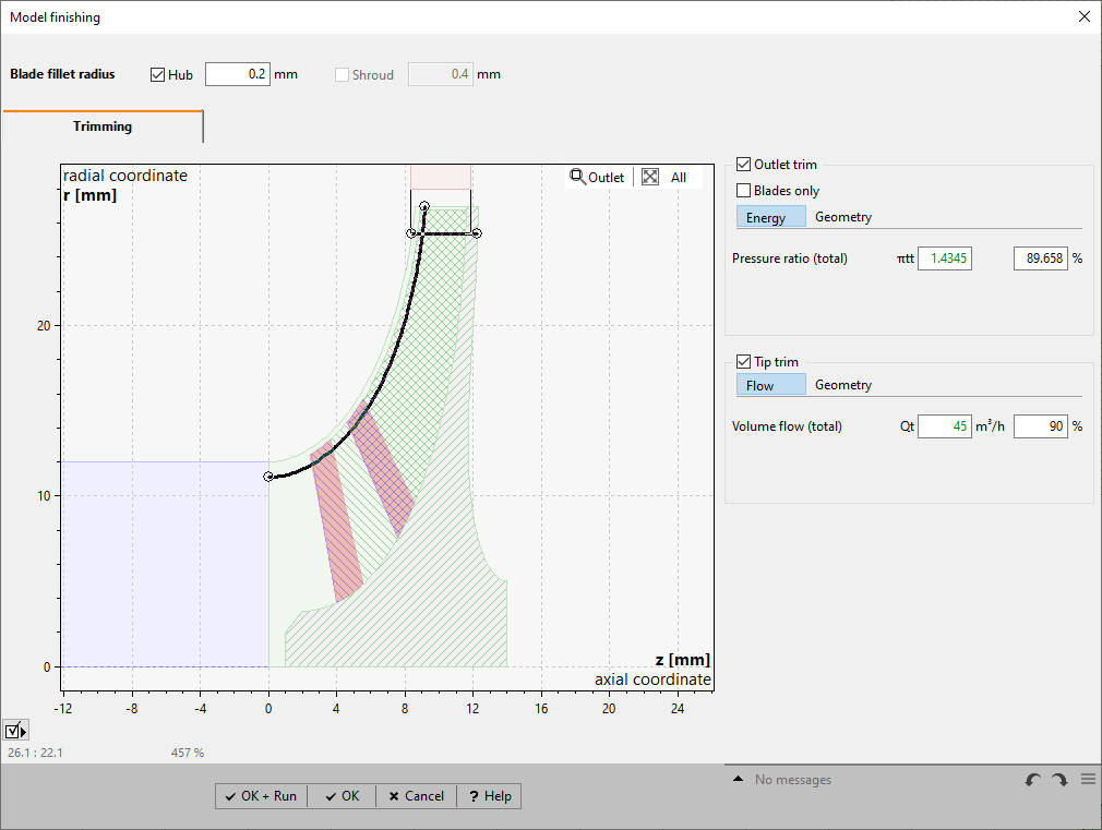
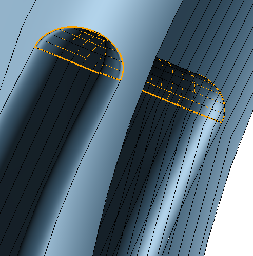
Impeller trimming
As part of "Finishing", completed impellers can be trimmed both radially or meridionally in order to adapt energy transmission and/ or flow rate.

Improved design of meridional solid, secondary flow path
Extensively modernized 2D diagram,
All control points available via batch mode

Duplication of components
Components can be duplicated within the current project,
Automatic adpation of z-position,
Multi-selection possible to duplicate complete stages
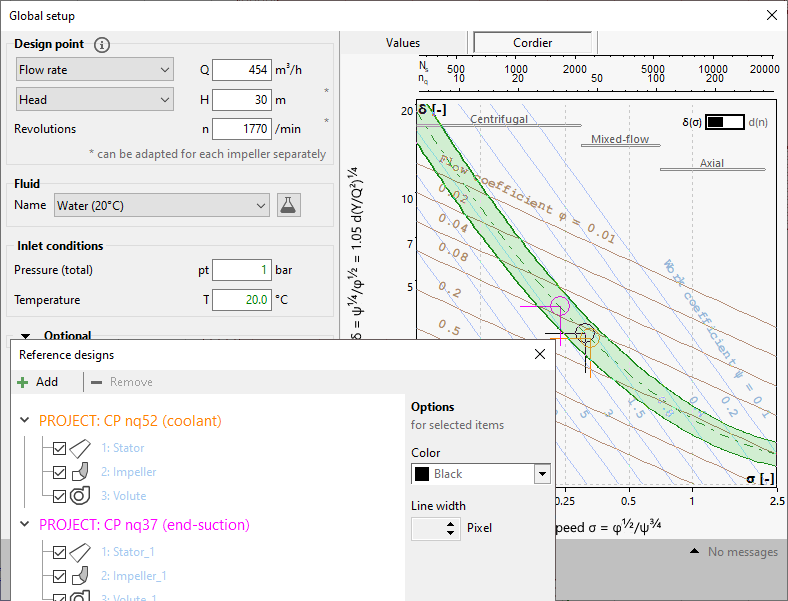
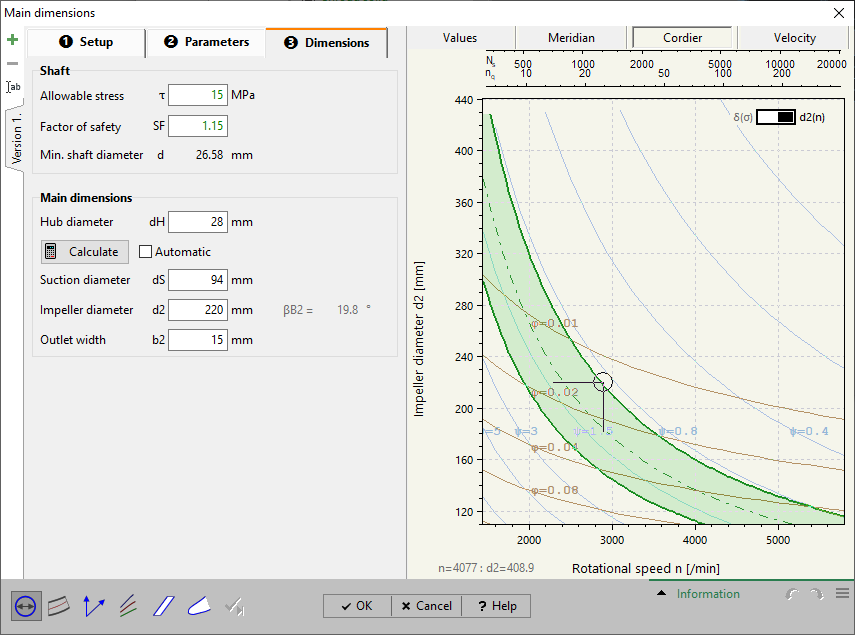
Reference designs within Cordier diagram
The position of reference designs in the Cordier diagram (Global Setup, impeller Main Dimensions) is displayed with additional markers.
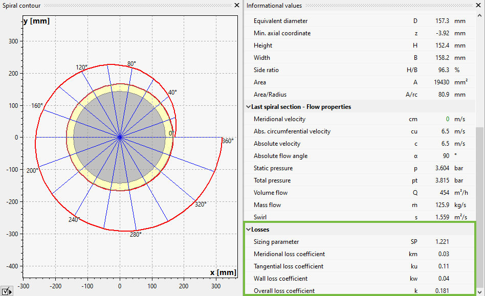
Loss coefficients for volutes
Calculation of loss coefficients and "Sizing parameter" according to the theory of Aungier.
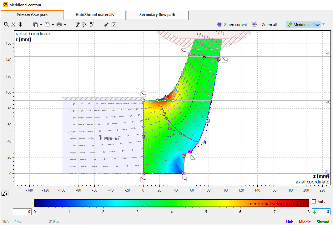
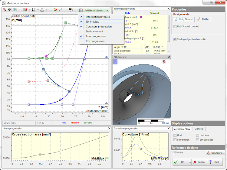
Customization of meridional flow scale
Min. and max. values of the scale can be determined not only automatically, but also manually.
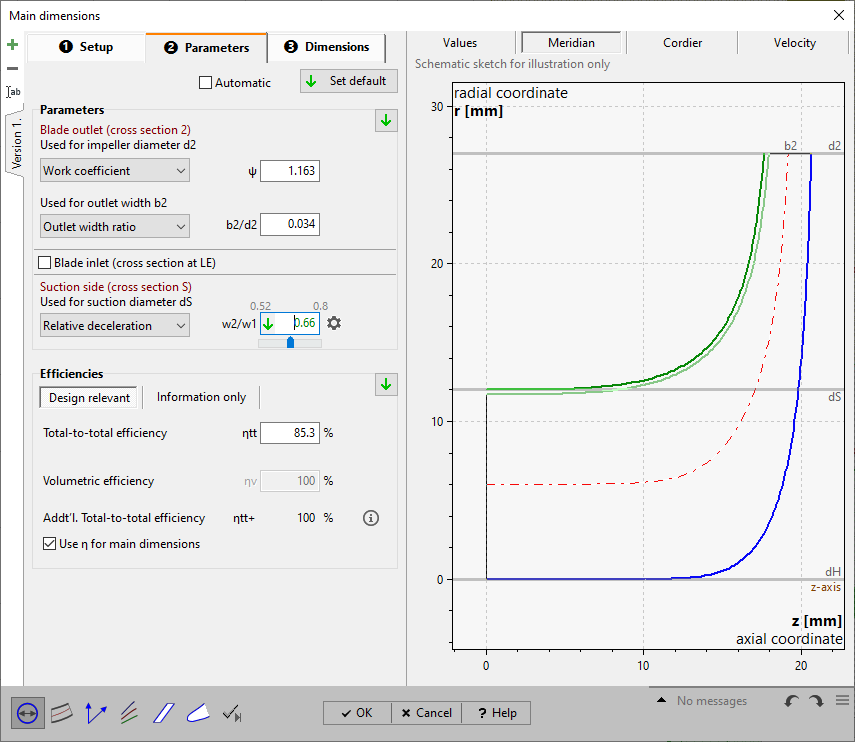
Specification of relative deceleration for centrifugal compressors
The deceleration ratio of relative flow w2/w1 can be used for the calculation of the suction diameter dS of centrifugal compressors optionally.
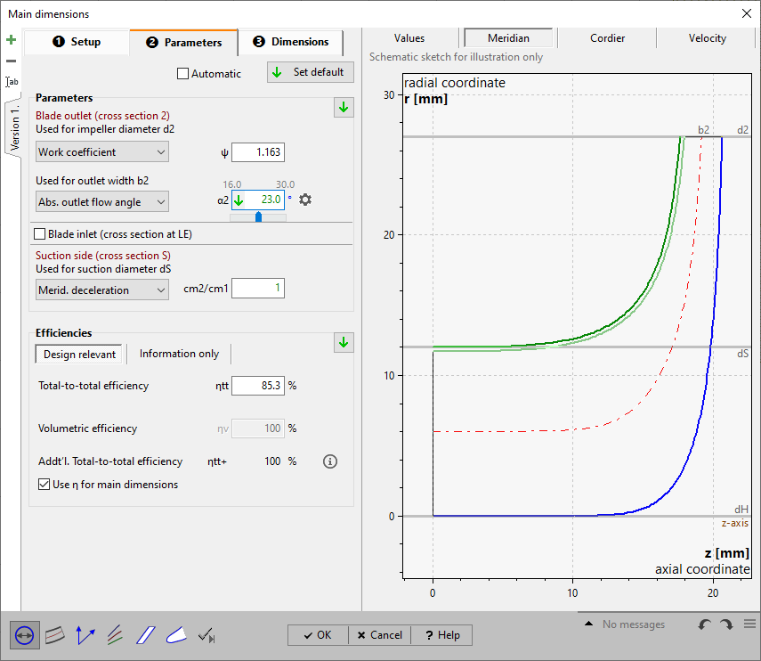
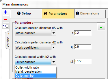
Specification of discharge angle for centrifugal compressors
The angle of absolute flow at impeller outlet α2 can be used for the calculation of outlet width b2 optionally.

Improved SimScale export
Complete flow region as a single solid,
Automatic identification of rotating zone,
Specification of meshing and solver parameters
CFturbo 2022 R2
November 2022
Segment of Solid and Secondary flow path
Rotational symmetric segment geometry is not only available for main flow path but for solid body and secondary flow path.
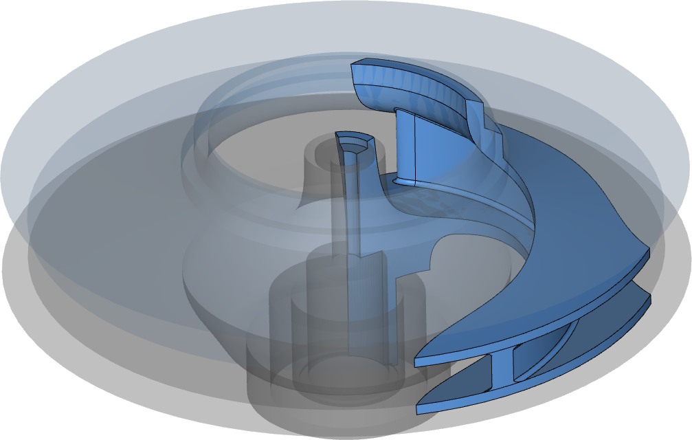
Barske impeller
Use of specific design method for pump impeller with very low specific speed by a new impeller type.

Flexible z-positioning of diffuser outlet
Arbitrary shift of diffuser outlet in z-direction.
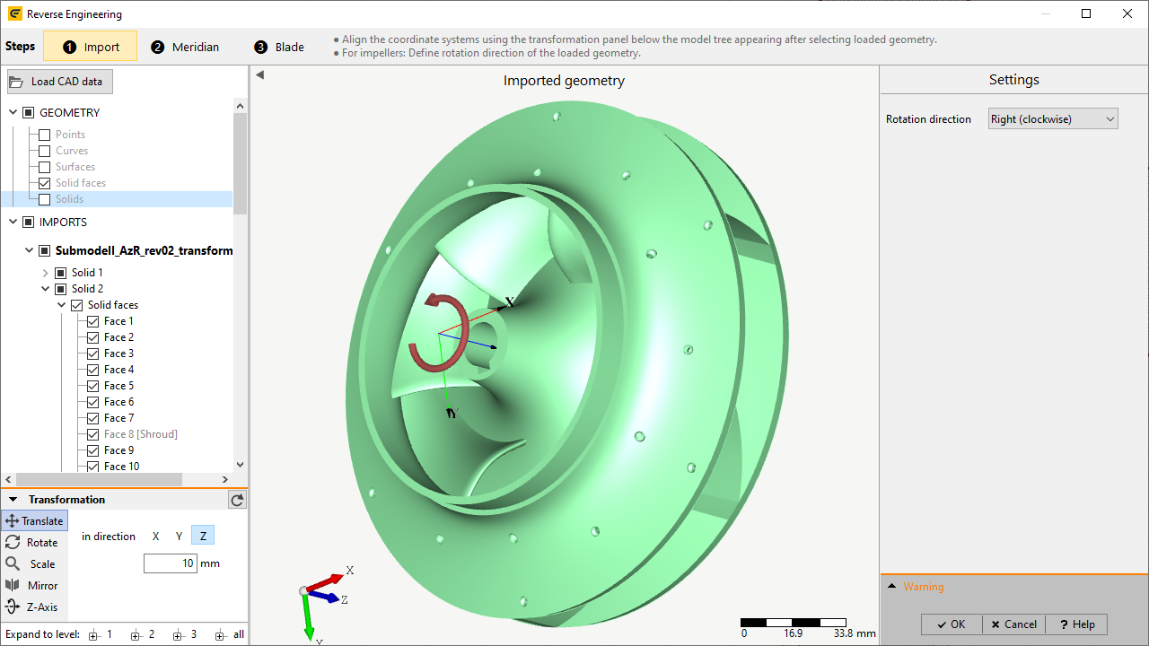
Specify and display direction of rotation during Reverse Engineering
Rotational direction of impeller is illustrated by an arrow around the z-axis and can be toggled.
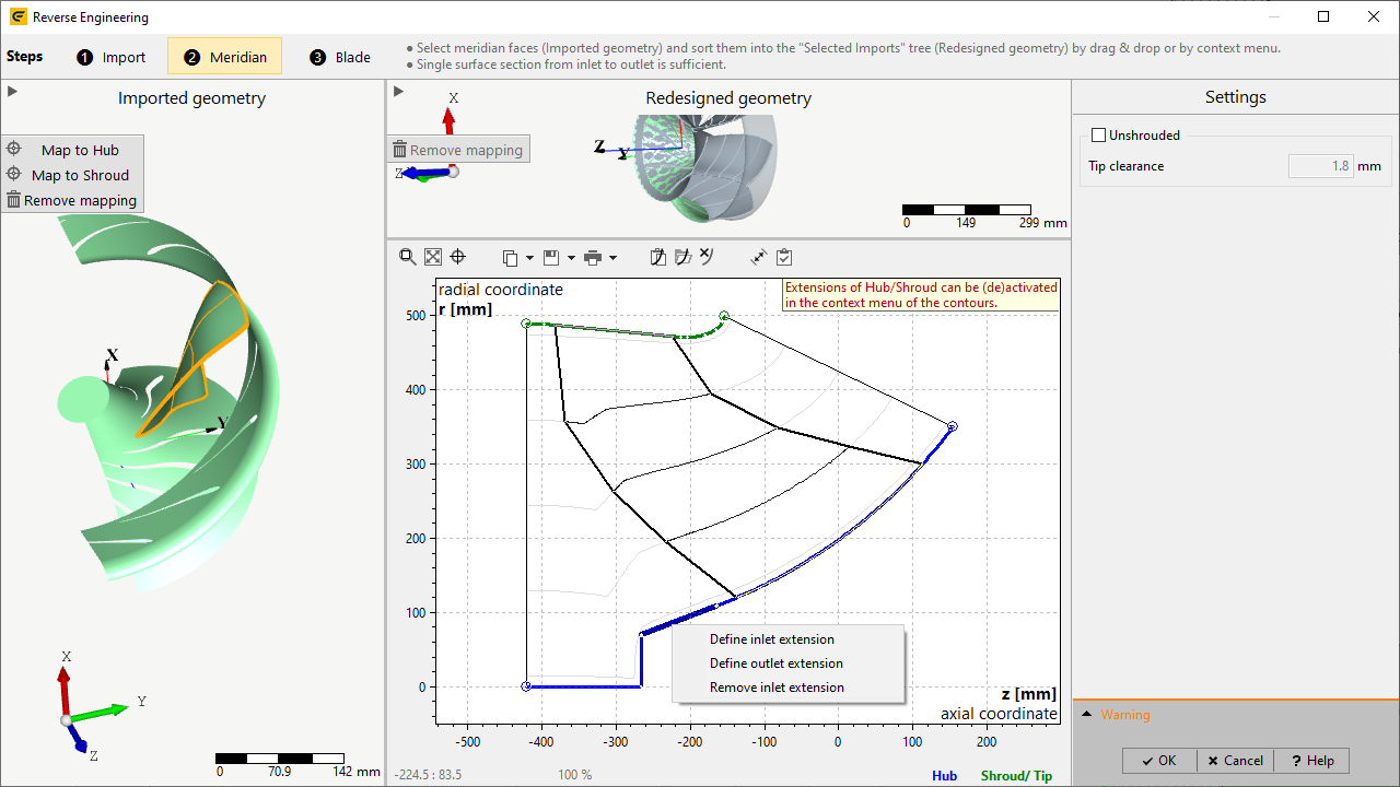
Support of hub extension during Reverse Engineering
Analogous to shroud, extensions can be defined at hub in order to ensure correct blade detection.
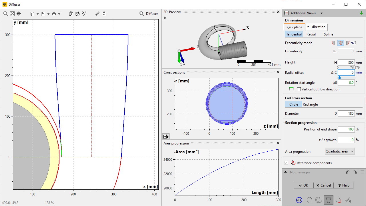
"Radial offset" for volute diffuser
Radial offset is specified in diffuser design step and is therefore available for all cutwater shapes (also "Fillet").
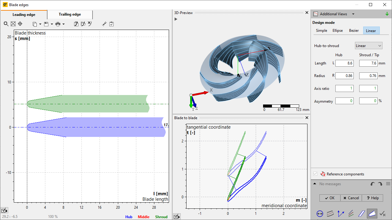
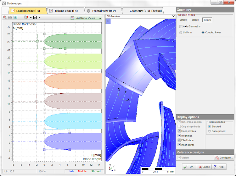
Linear blending of blade edge definitions from hub to shroud
For design modes "Ellipse" and "Linear" different geometries can be specified at hub and shroud, between which a linear blending is realized.
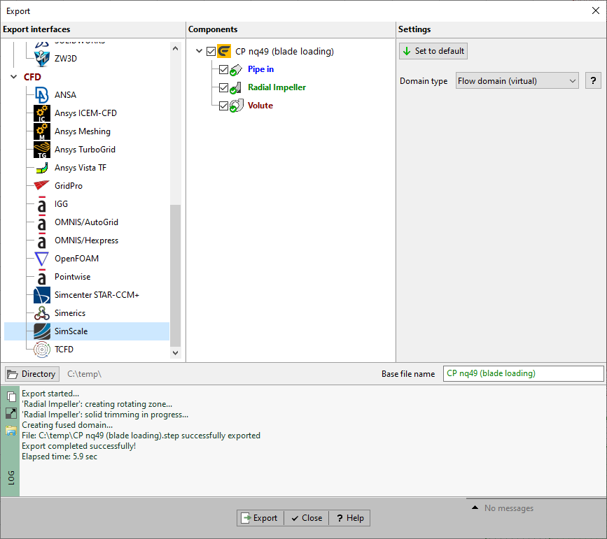
SimScale export interface
Geometry is exported in such a way that an immediate start of simulation in SimScale is possible.
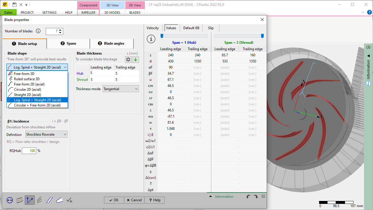
Simplified blade shapes for impeller
The blade shapes "Log. Spiral + Straight 2D (axial)" and "Circular + Free-form 2D (axial)" available so far for radial diffusers only, can now also be used for centrifugal impellers.
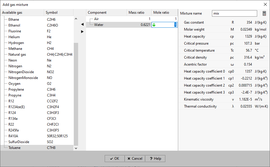
Alternative definition of gas mixtures
As an alternative to the mass fractions, the composition can also be determined by the mole fractions.
CFturbo 2022 R1
May 2022
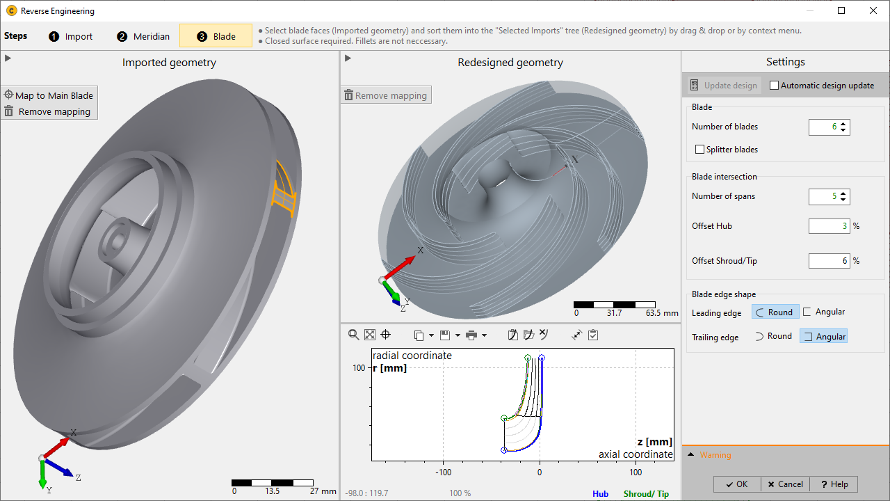
Reverse engineering
Import of CAD models of impellers/stators and semi-automatic detection of sub-surfaces. The result is a parametric CFturbo model that can be modified in all details by the user.
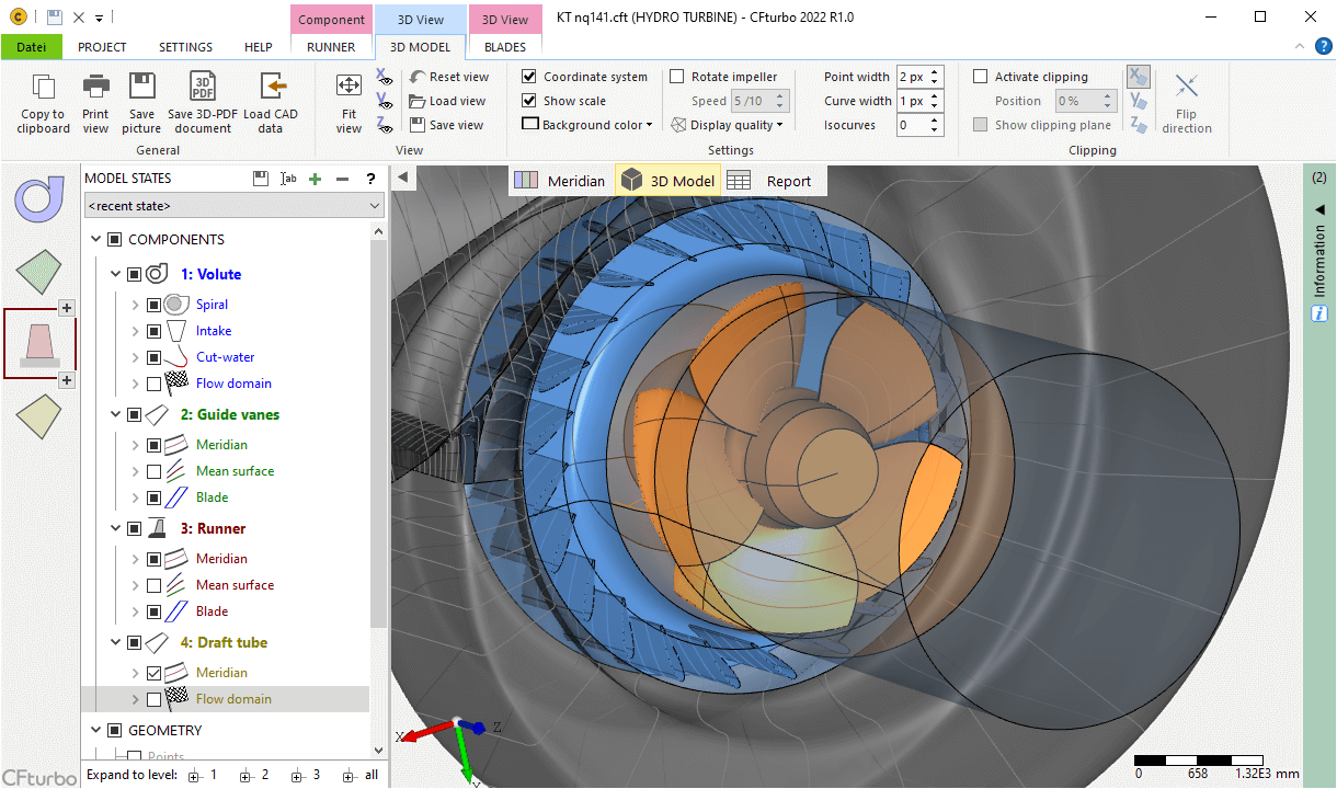
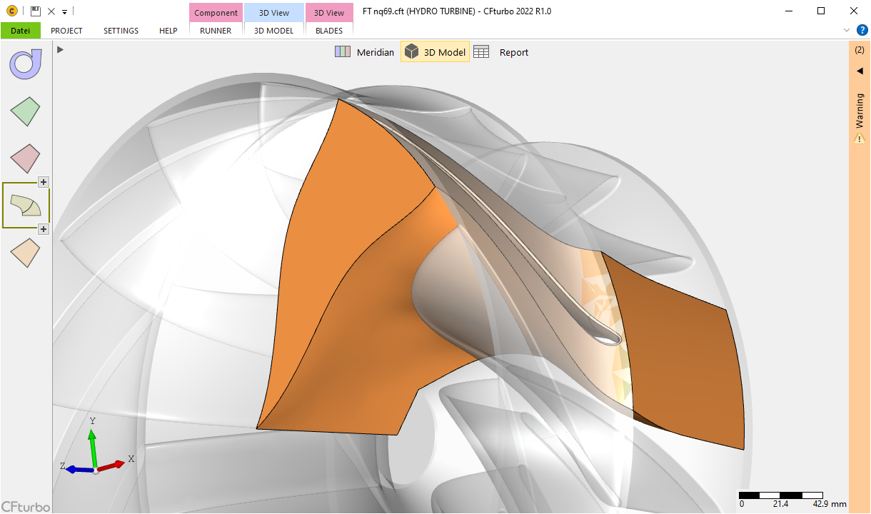
New module: Kaplan Turbine
With Kaplan turbine runner design, axial water turbines can now be designed, incl. full 3D modeling and multiple interfaces to CAD and CFD.
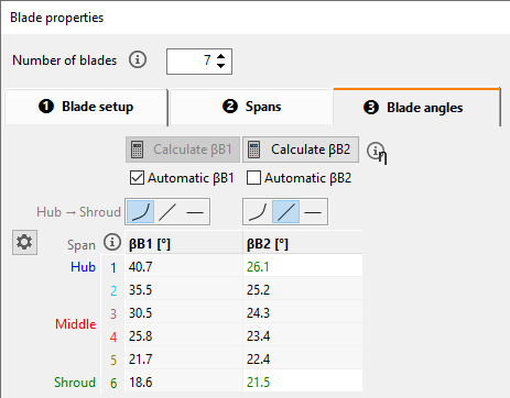
Separate automatic calculation of blade angles
Automatic calculation can be activated separately for the blade angles at leading and trailing edge. This offers advantages for optimization in particular.
Improved generation of the blade segment
A continuous periodic surface is generated, which is more general and thus more stable. This is the precondition for the future segmentation of the secondary flow path.
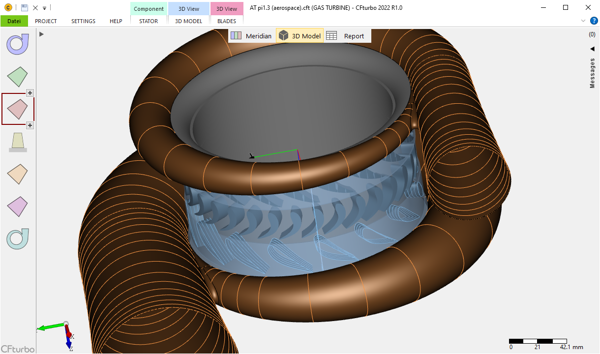
Inlet and outlet volute casing within a project
Application is especially typical for axial turbines.
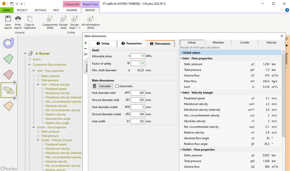
Availability of more informative values in dialogs and in the report
Values are displayed in collapsible areas in the dialogs. All informative values are also available in the project report.
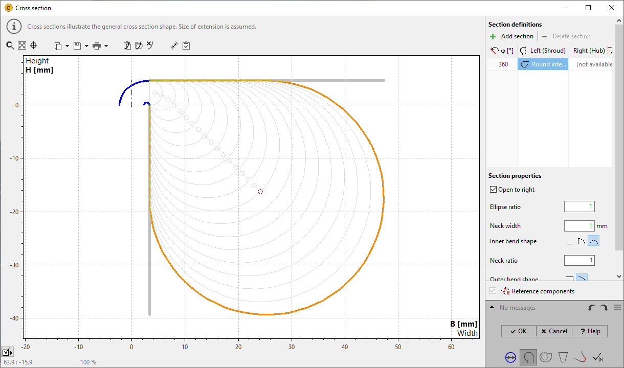
Internal volutes with selectable opening direction
Internal volutes can optionally develop to the left (against z-direction) or to the right (in z-direction).
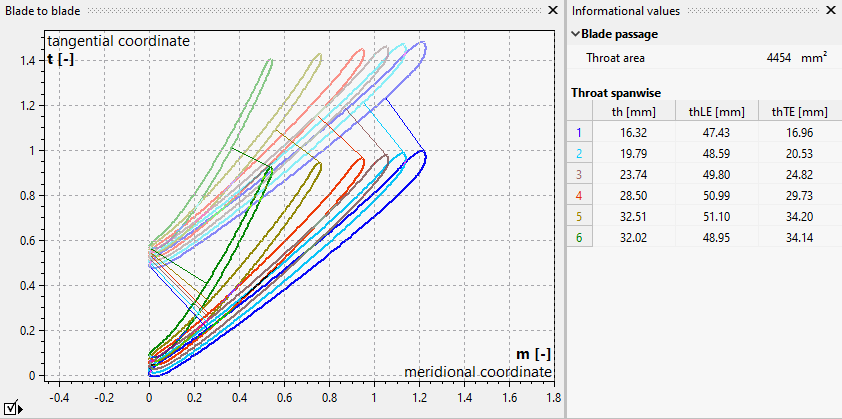
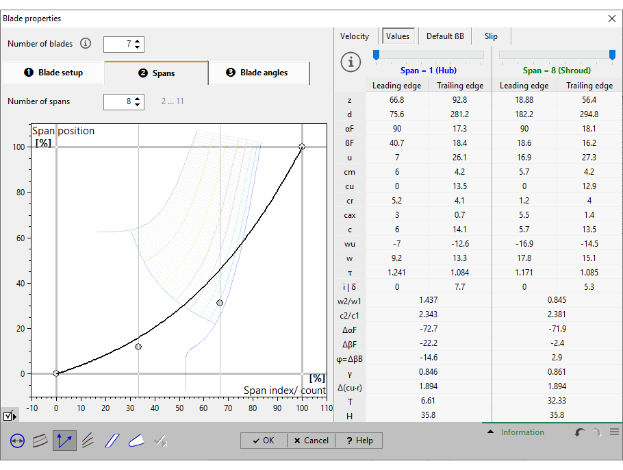
Improved calculation of the throat area between blades
In addition to the graphical representation, the numerical values for each span are displayed in tabular form.
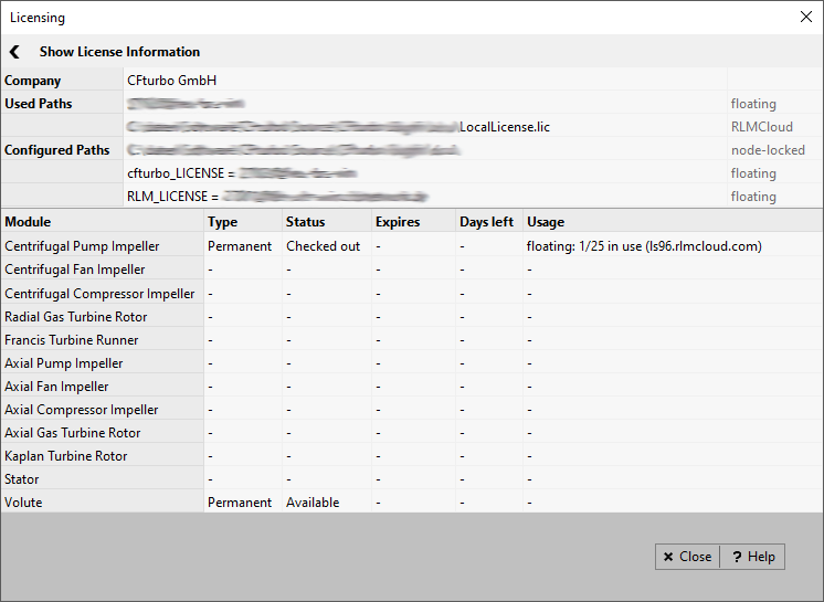
Cloud-based licenses
In addition to local (nodelocked) licenses and floating licenses on the company's own license servers, licenses can also be provided via license servers in the cloud. This eliminates the need to operate your own license server.
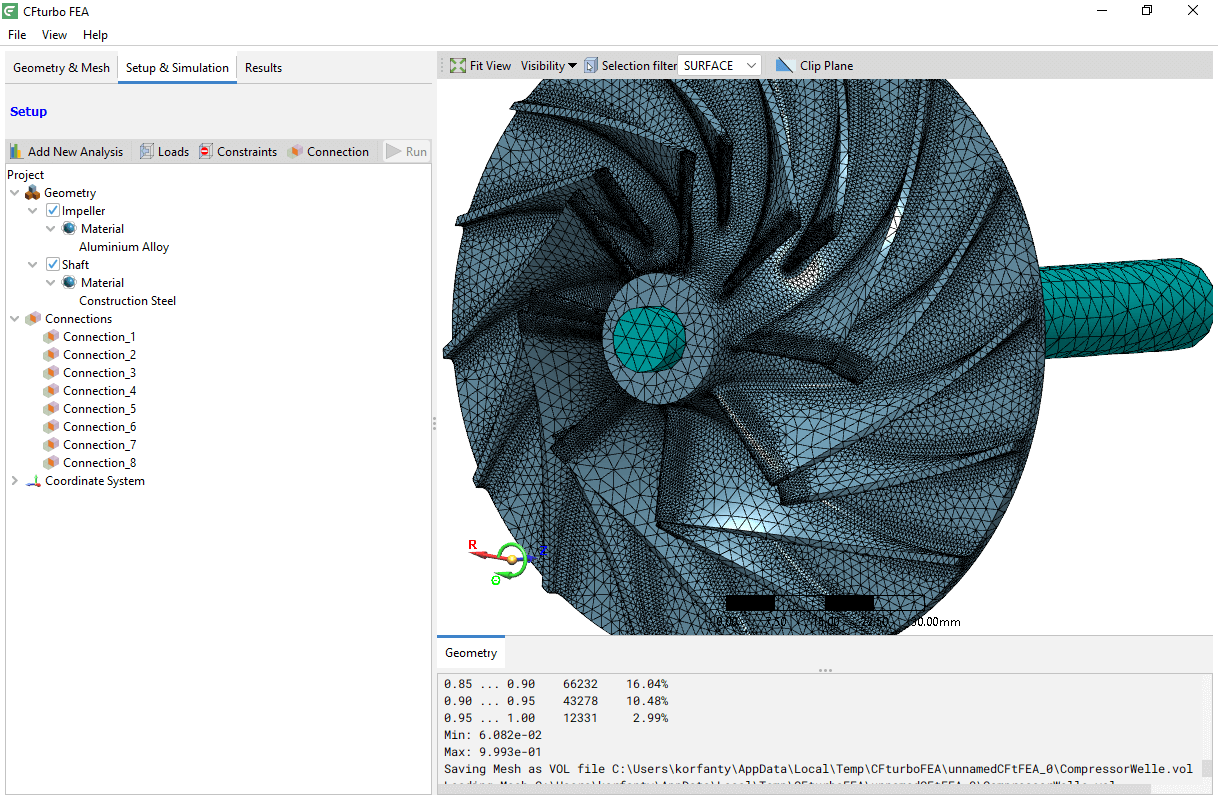
CFturbo FEA: Multibody
Static analyses for entire assemblies consisting of several components possible
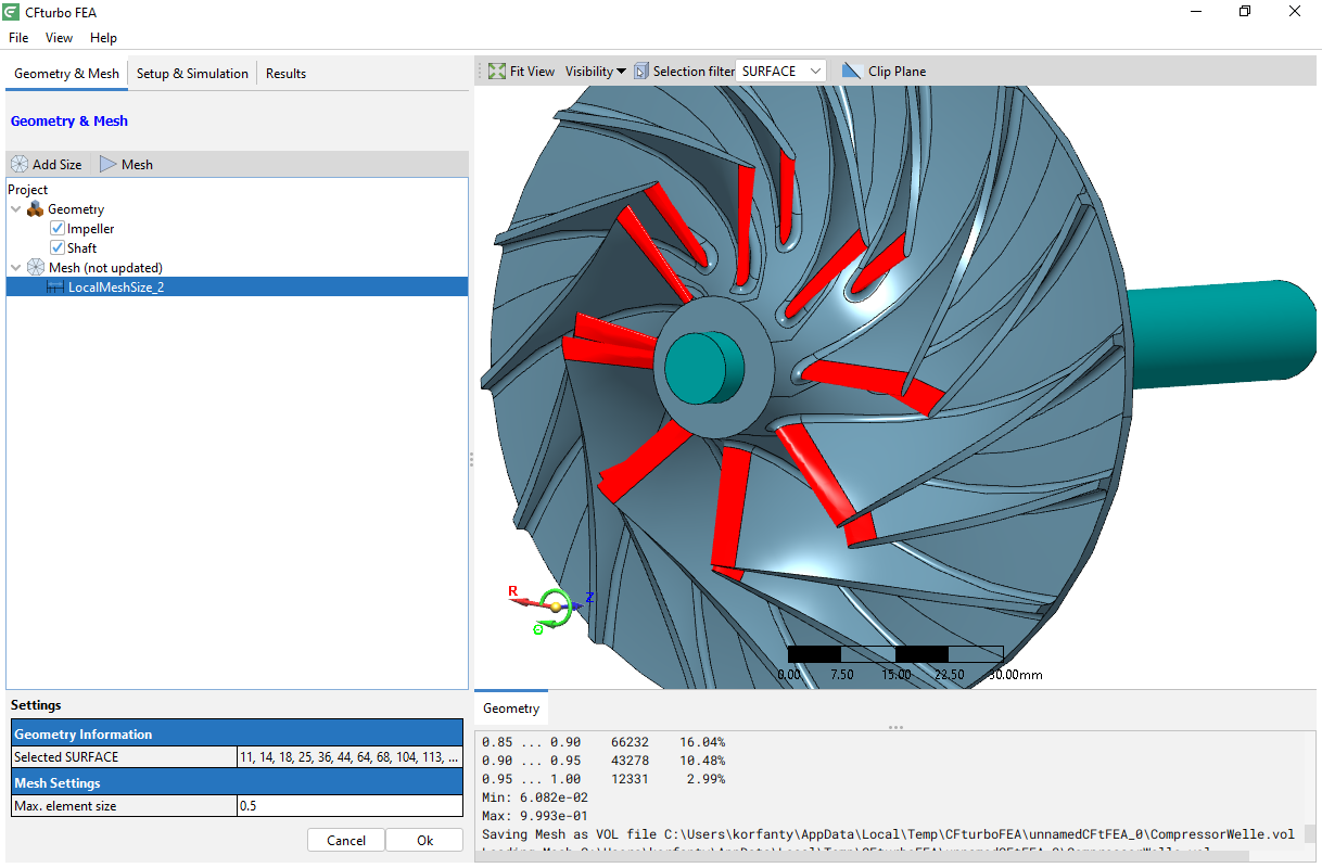
CFturbo FEA: Local mesh parameters
Local mesh parameters (element sizes) can be assigned for any number of surfaces.
CFturbo 2021 R2
November 2021
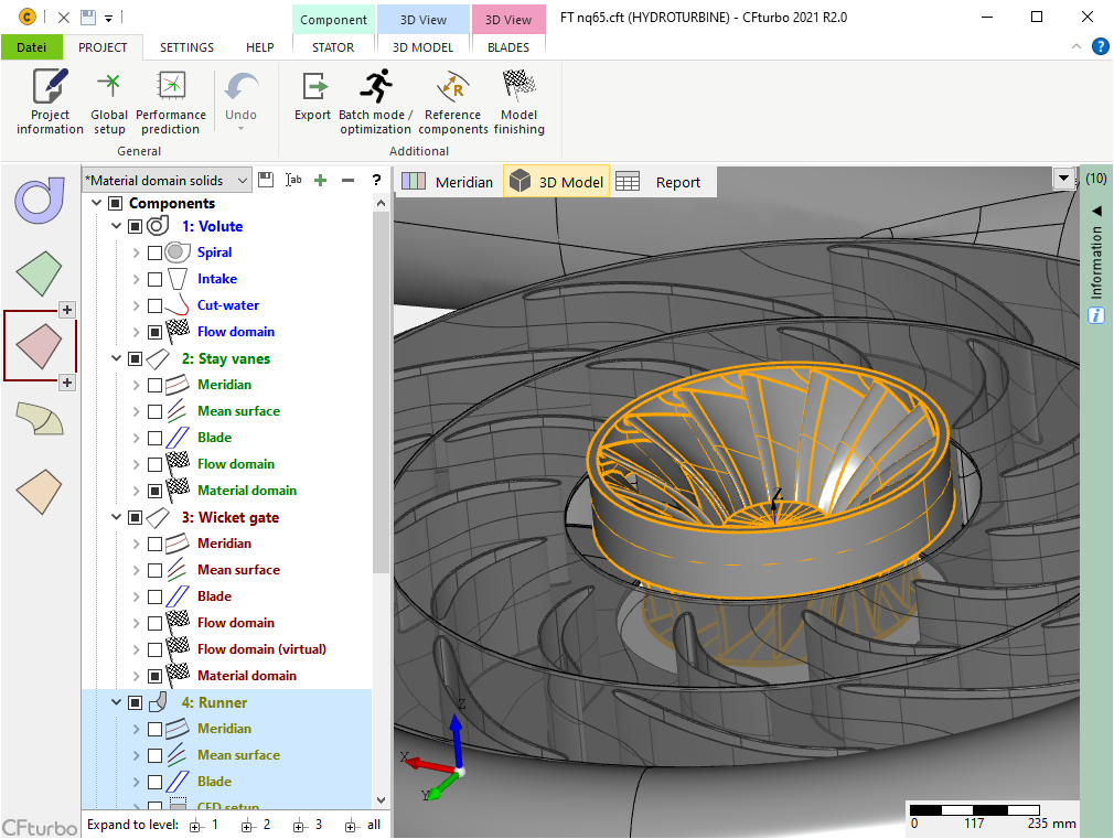
New module: Francis turbine
With Francis turbine runner design, radial/ mixed-flow water turbines can now be designed, including full 3D modeling and multiple interfaces to CAD and CFD.
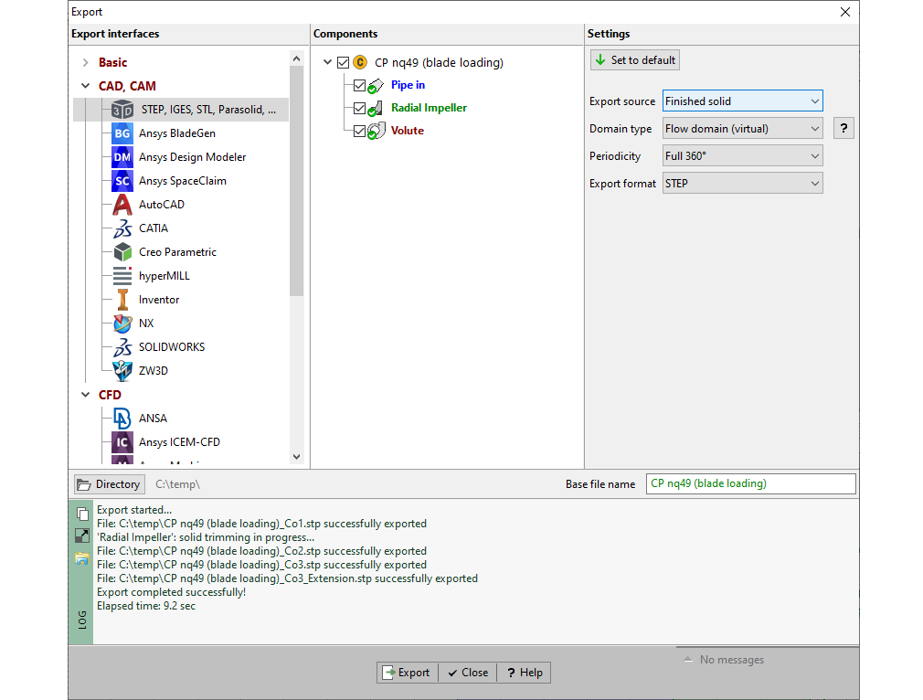
New export structure for neutral 3D formats
The new structure additionally allows the export of "Finished solids" and the selection of the domain type, so that batch runs in the context of DoE or optimization are also possible with these interfaces.
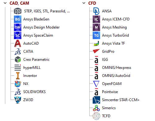
New export interfaces
Ansys Design Modeler
OMNIS/Hexpress
GridPro
ZW3D
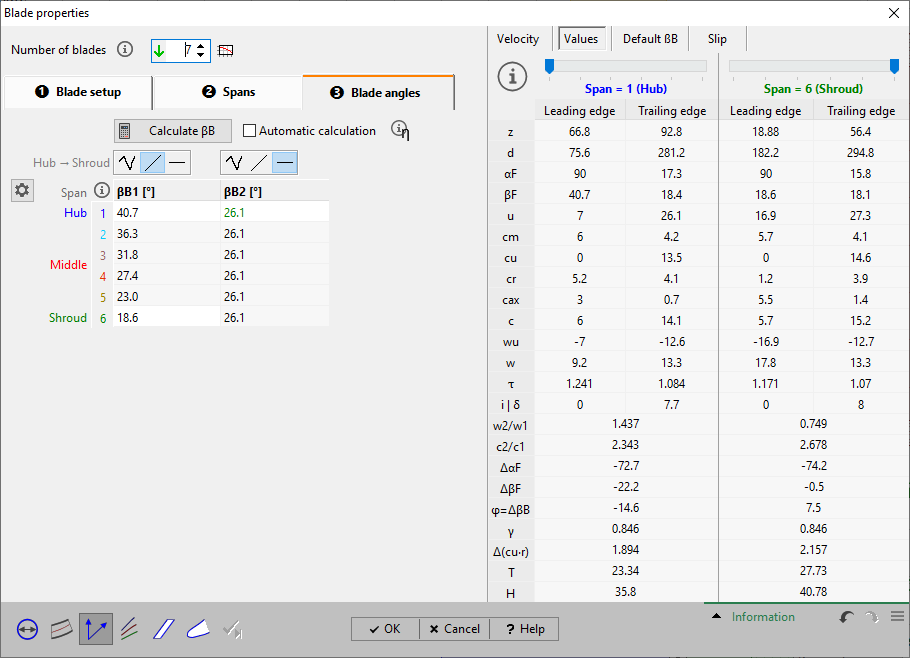
Separate blade angle distributions for leading and trailing edge
The separate distribution simplifies especially the optimization by reducing the parameters, so that computation time can be saved.
(applies analogously also to profile properties)
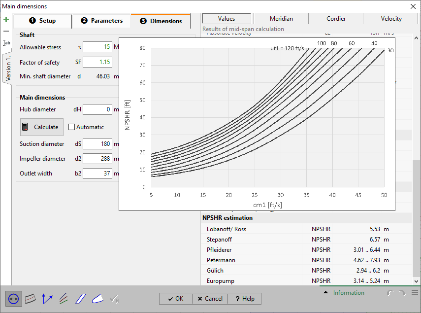
NPSHR prediction according to Lobanoff/ Ross
Complementary to the already existing 5 prediction models using the diagram published by Lobanoff/ Ross.
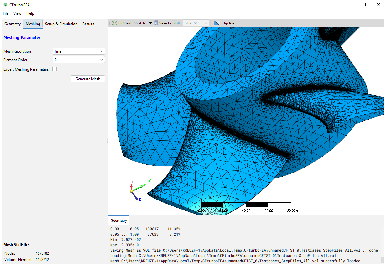
Software "CFturbo FEA"
The software allows the calculation of static stresses and deformations as well as modal analyses. "CFturbo FEA" is available free of charge to all active CFturbo users.
CFturbo 2021 R1
June 2021
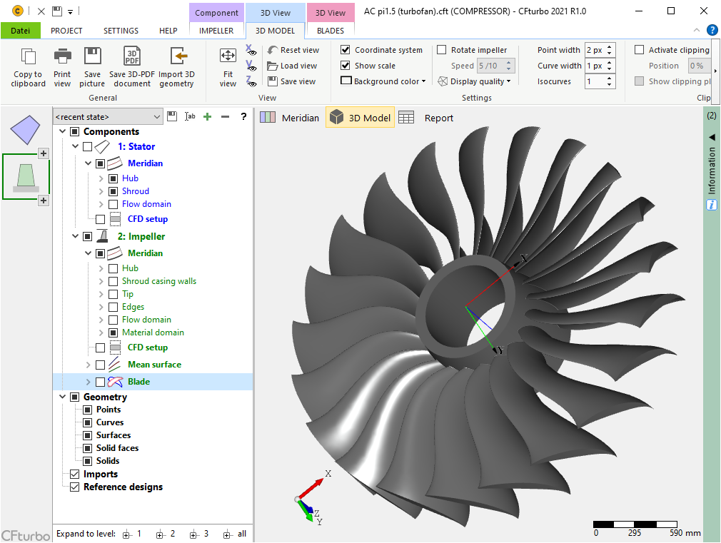
New module: Axial compressor
With axial compressors a gap in compressor design has been closed. Multi-stage axial compressors can now be designed, using the existing perfect or real gas models.

Main dimensions: Turbine initial design according to Balje's method
With the help of a special dynamic diagram (similar to Cordier) important quantities like efficiency and blade height can be derived. Flow angles can also be estimated, so that all velocity triangles and the complete thermodynamic state can be calculated.

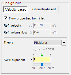
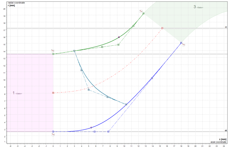
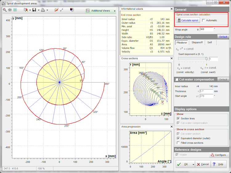
Volute: Use of interactive design curves
Instead of the previously displayed frontal view of the spiral, the corresponding design curves are shown. These can result from the design specifications (Pfleiderer, Stepanoff), or allow interactive direct modification of the geometry.
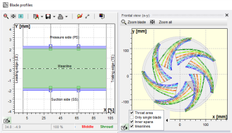
Blade properties: Flexibilization of span positions
Until now, the blade design curves (spans) were distributed linearly between hub and shroud. Now, as an option, any adjustment of the distribution is possible, so that concentration near the outer, middle or inner span is available.
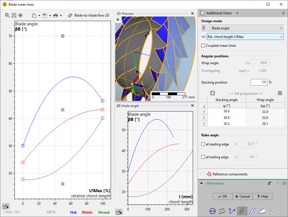
Mean lines: Using the blade chord length as a parameter for defining the β-distribution
When designing mean lines by specifying a distribution of blade angles β, it can be advantageous to plot it over the chord length. This possibility now exists as an alternative to the previous definitions of the x-axis.
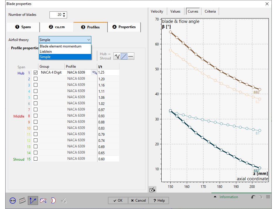
Blade properties: New "Simple" airfoil design mode
The simple design mode is offered as an alternative to the existing modes. It allows the calculation of the chord length l and the stagger angle γ by specifying the solidity l/t using the shock-free inflow and the Euler equation.
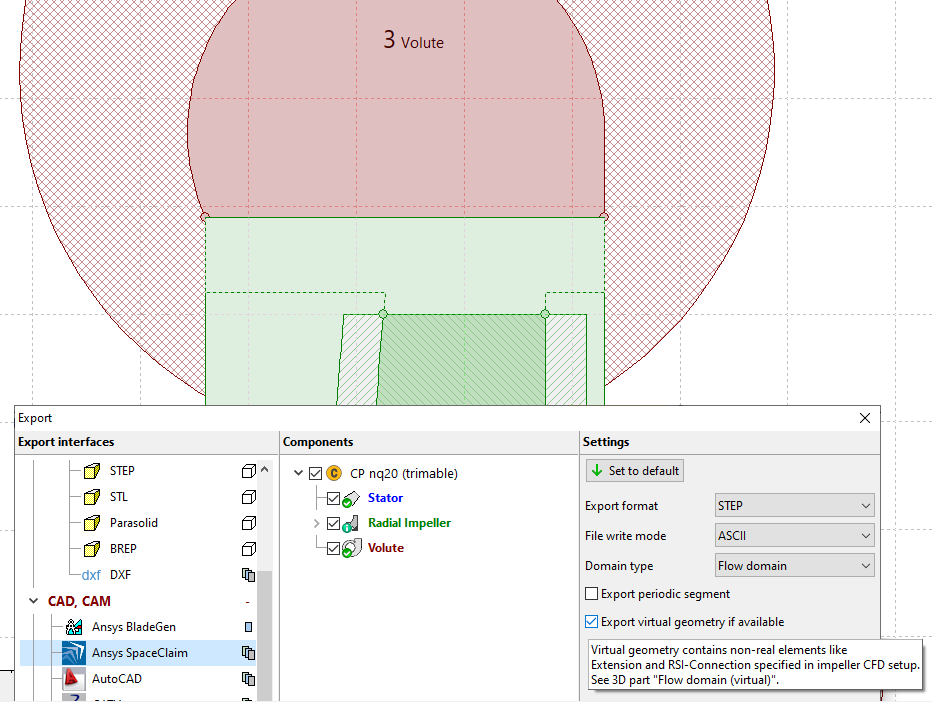
3D model, export: Simultaneous design of real and virtual geometry
Previously, it was only possible to design either the real geometry (including secondary flow path) or the virtual geometry (simplified connection of neighboring components). This is now possible in parallel, so that both variants are available at the same time within a project and can be used in CFD workflows.
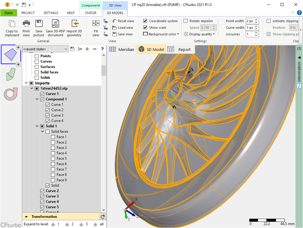
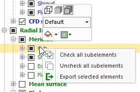
3D model: Detect all individual elements of imported geometries
The hierarchical representation of all imported individual elements (points, curves, surfaces) makes it easy to adjust their visibility or display properties. This facilitates geometry preparation for comparison of different models and reverse engineering.
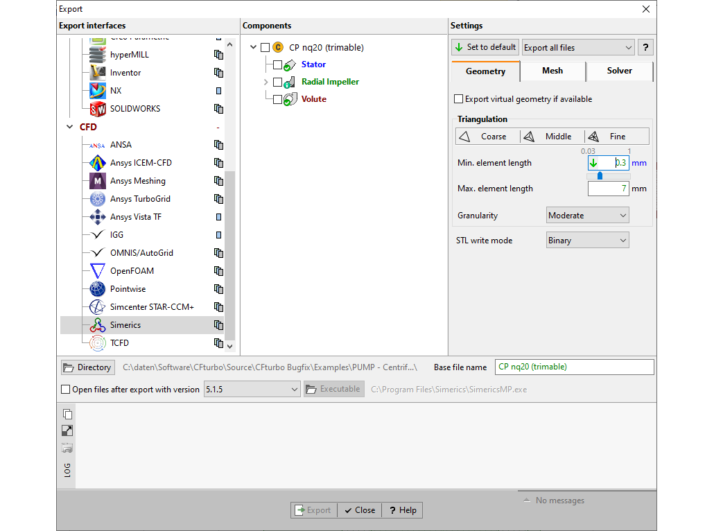
Export: Display of all export settings directly in the export window
This makes checking or adjusting the export settings for the selected interface much easier and clearer.
CFturbo 2020 R2
November 2020
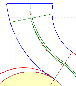
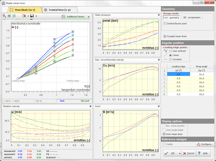
Composite mean lines, optional with βB = const.
In a particular diameter range at leading and/ or trailing edges, composite mean lines can be designed to force constant regional blade angle βB1 and/ or βB2.
Enhanced Cordier diagram
Switching between relative and absolute values is available. Absolute values in the Cordier diagram may be more intuitive for some CFturbo users when evaluating the calculated impeller's main dimensions.

Parasolid export with surface names included
The named surface export for Parasolid models is an essential improvement for many CAD/CAE software interfaces and a more streamlined workflow set-up.

Sharp Cutwater for internal volutes
From now on, the very special internal volutes can be directly used for CFD-simulations since there is a watertight model available for export.
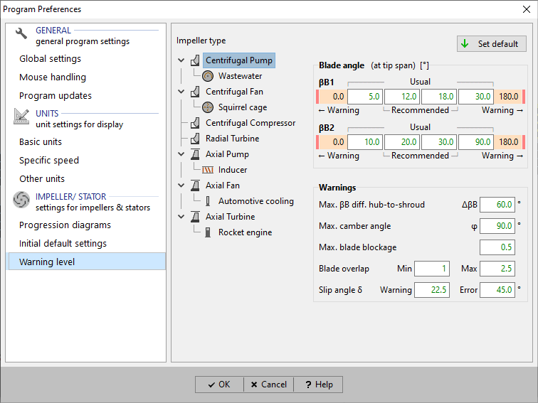
User specification of limit values for warnings
The user can specify his warning limits for some essential parameters in the preferences for his personal use.
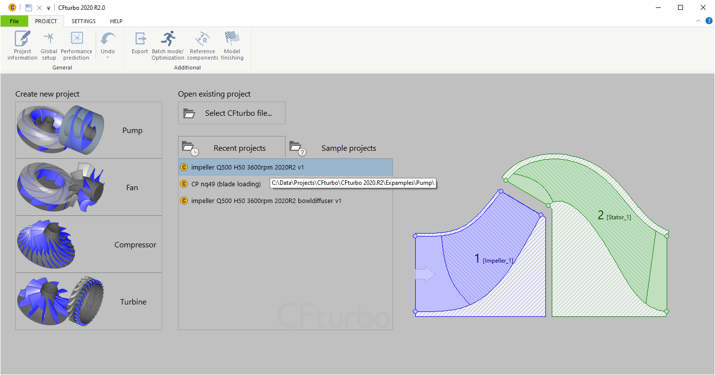
Meridional preview for recent and sample projects
The CFturbo start screen shows a simplified meridional sketch of the recent and sample models, which should assist to re-open the right file for further project work.
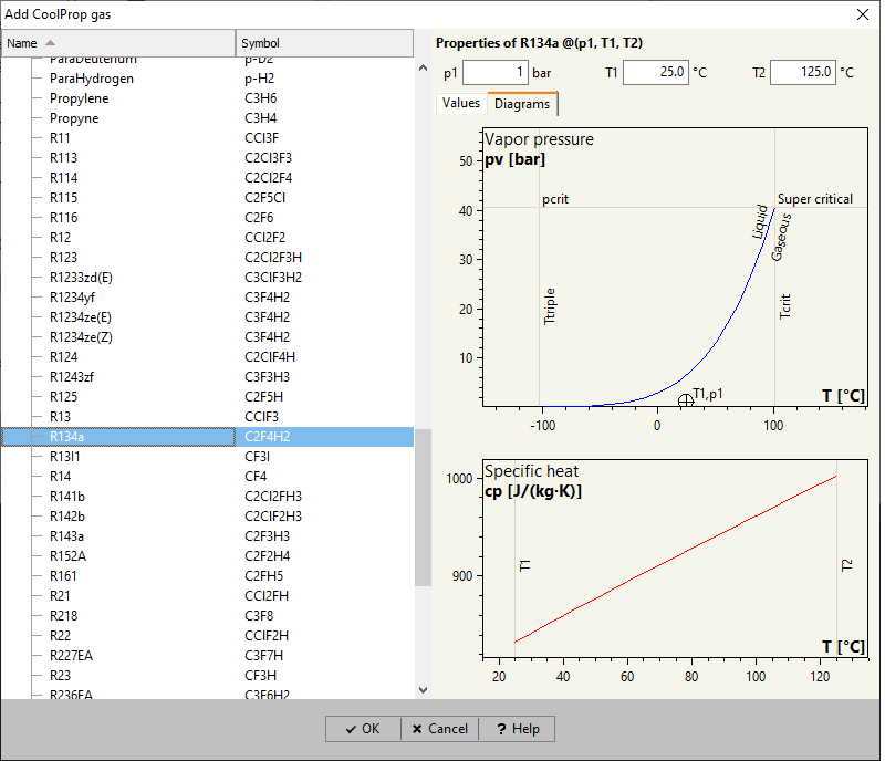
Additional diagrams for CoolProp fluids
Diagrams for vapor pressure and specific heat are available for two-phase fluids selected from the CoolProp database.
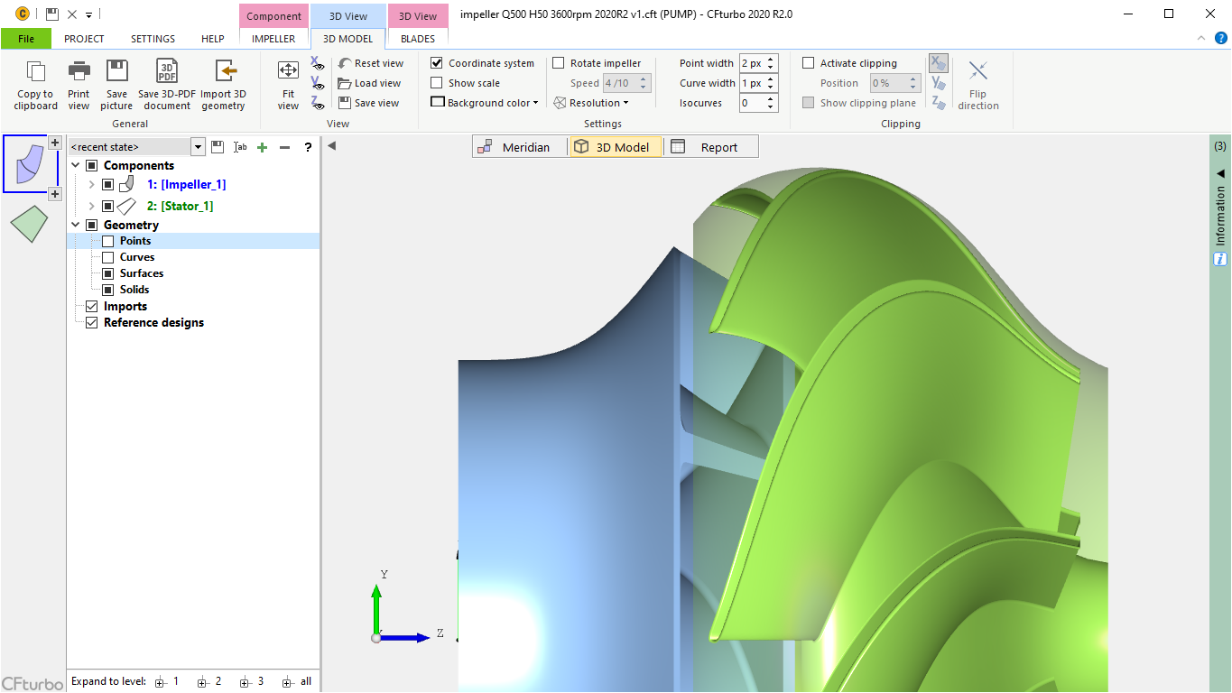
Enhanced model finishing
The 3D-CAD-model finishing has been improved for fillets in general and for leading edges of bowl diffusers in particular to ensure high-quality export files.
CFturbo 2020 R1
May 2020
Inverse blade design
Additional method for blade design based on blade loading distribution. A 3D-freeform blade shape can be described by fewer parameters which could be useful especially for design exploration and optimization.
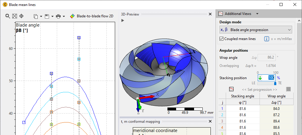
Blade angle distribution of mean lines
Flexible stacking position for β mean line design mode. By its definition the blade can be fixed on any position, which provides a much higher geometric flexibility for the blade design in the widely used meanline design mode.
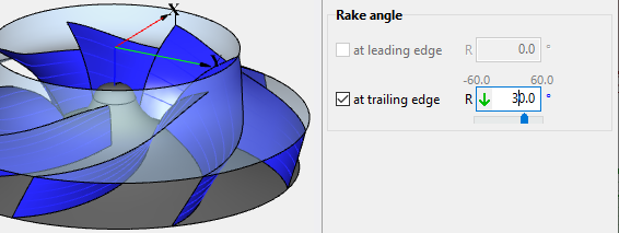
Rake angle
Explicit definition of rake angle at leading and/or trailing edge. It's much easier and accurate compared to the previous version.
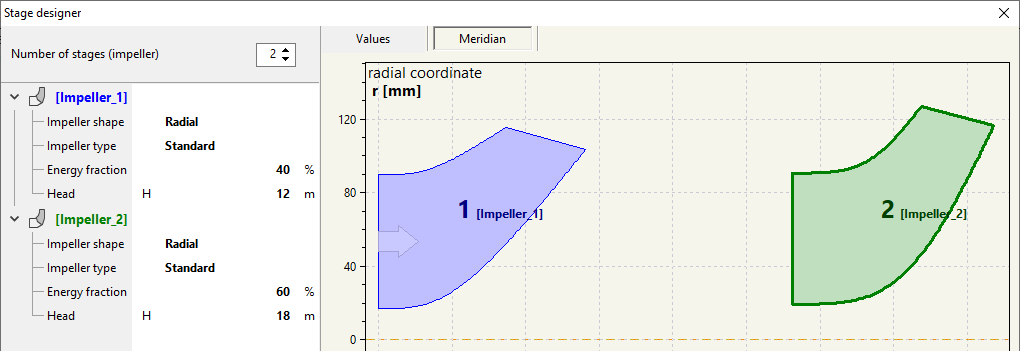
Enhanced design of multistage machines
New Stage-Designer to simplify the design of multi-stage machines with up to 3 stages. Together with the new coupling/ decoupling option for turbomachinery components the modeling flexibility has been significantly improved.
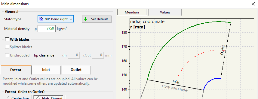
90° bends
Simplified generation of 90° bends (stators)
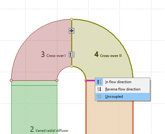
Decoupling of components
Optional decoupling of components to improve flexibility
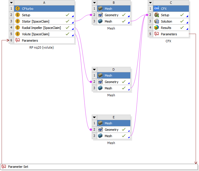
ANSYS Workbench
Further improvement of the workbench integration. The standardized ANSYS meshing system can be used, and an option for automated named selection of CFturbo components has been implemented.
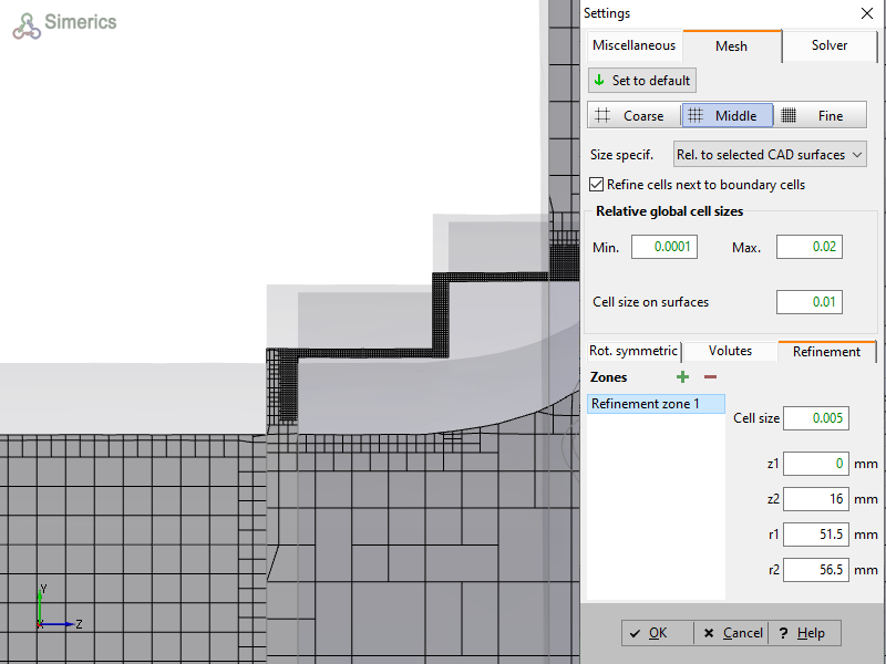
SimericsMP
Definition of mesh refinement zones. Thus the highly automated meshing becomes more flexible, especially for critical areas with expected high flow field gradients.
More optimization parameters for volutes
Number of design parameters has been enlarged that can be directly addressed for automated design exploration and optimization.
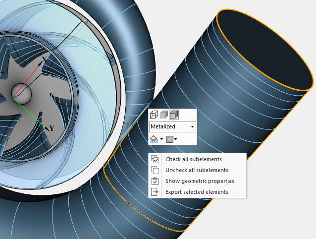
Object selection in 3D models
Like in any other general purpose CAD-systems, a CFturbo user can select and configure geometrical 3D elements directly in the 3D model view.
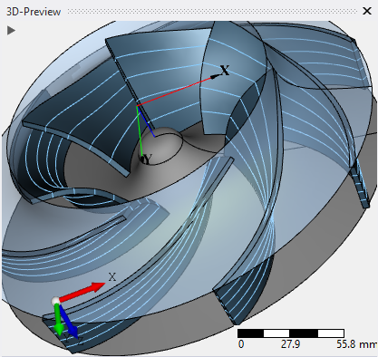
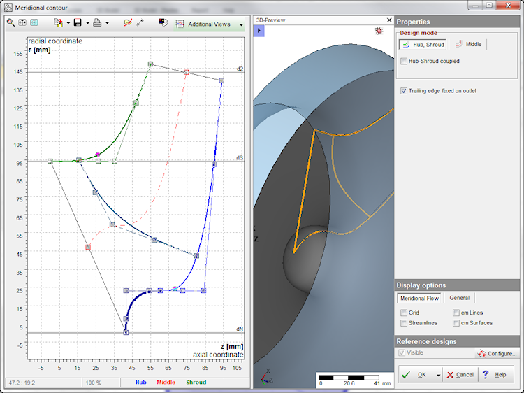
Improved 3D preview
More comprehensive preview of overall geometry in design dialogs.

Generation of 3D PDF
For the visible 3D model to use in Adobe Acrobat. The export of 3D PDF files will raise the information level when sending information about a specific CFturbo model to colleagues and partners, without exchaning 3D-CAD-files.

Axial impeller positioning
Simplified axial positioning of impellers within meridional design.
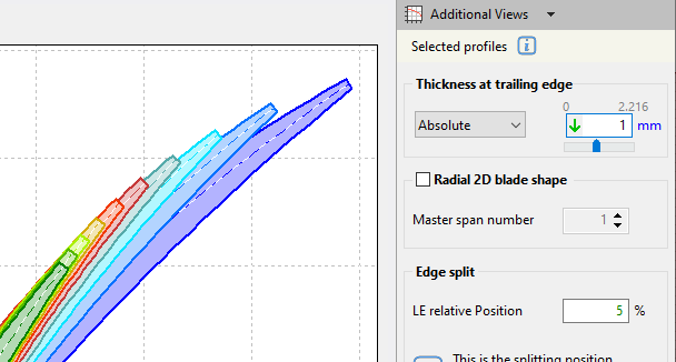
NACA profiles
Absolute definition of trailing edge thickness of NACA profiles.

Non-effective blade for comparison
Display of blade angle curve for the case of const. swirl
CFturbo 10.4
March 2019
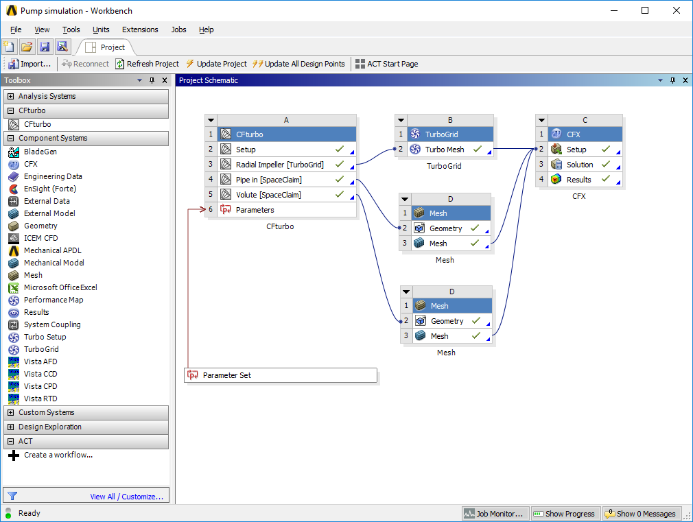
ANSYS Workbench
Parametric, bi-directional integration into ANSYS Workbench

ANSYS TurboGrid
Alternative export format for ANSYS TurboGrid: *.inf

Improved solid based interfaces
ANSYS Spaceclaim, ANSA, Pointwise

Parasolid
Import and export interface to Parasolid

hyperMILL
Export interface to hyperMILL (CAM software from OPEN MIND)
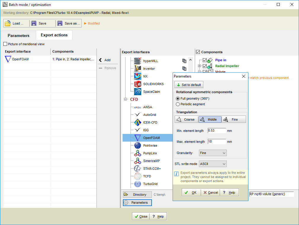
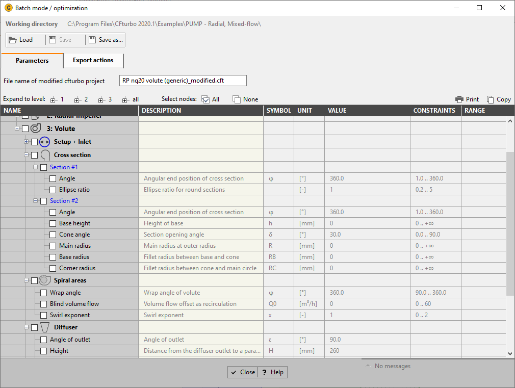
Export parameters in batch mode
All export parameters are available in batch mode

Opening batch mode files
Interactive opening of batch mode files *.cft-batch in addition to project files *.cft
Advanced Drag & Drop
For batchmode files, imported 3D files, and reference projects
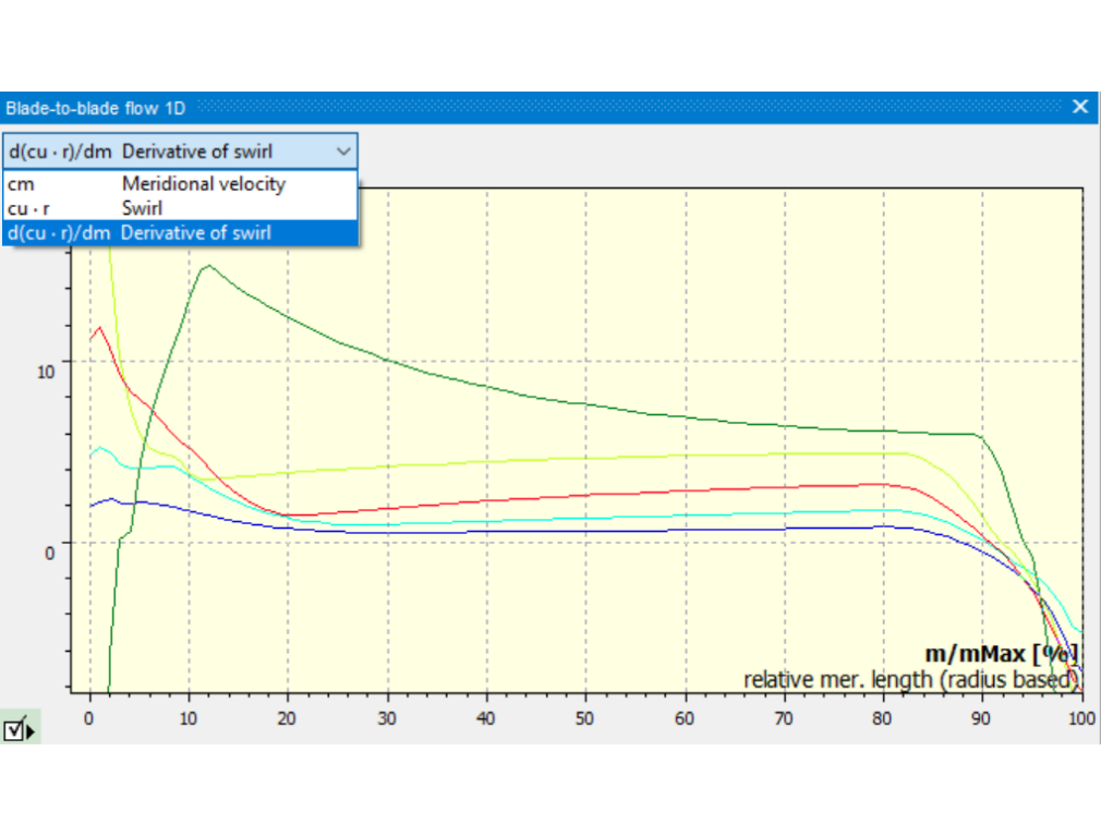
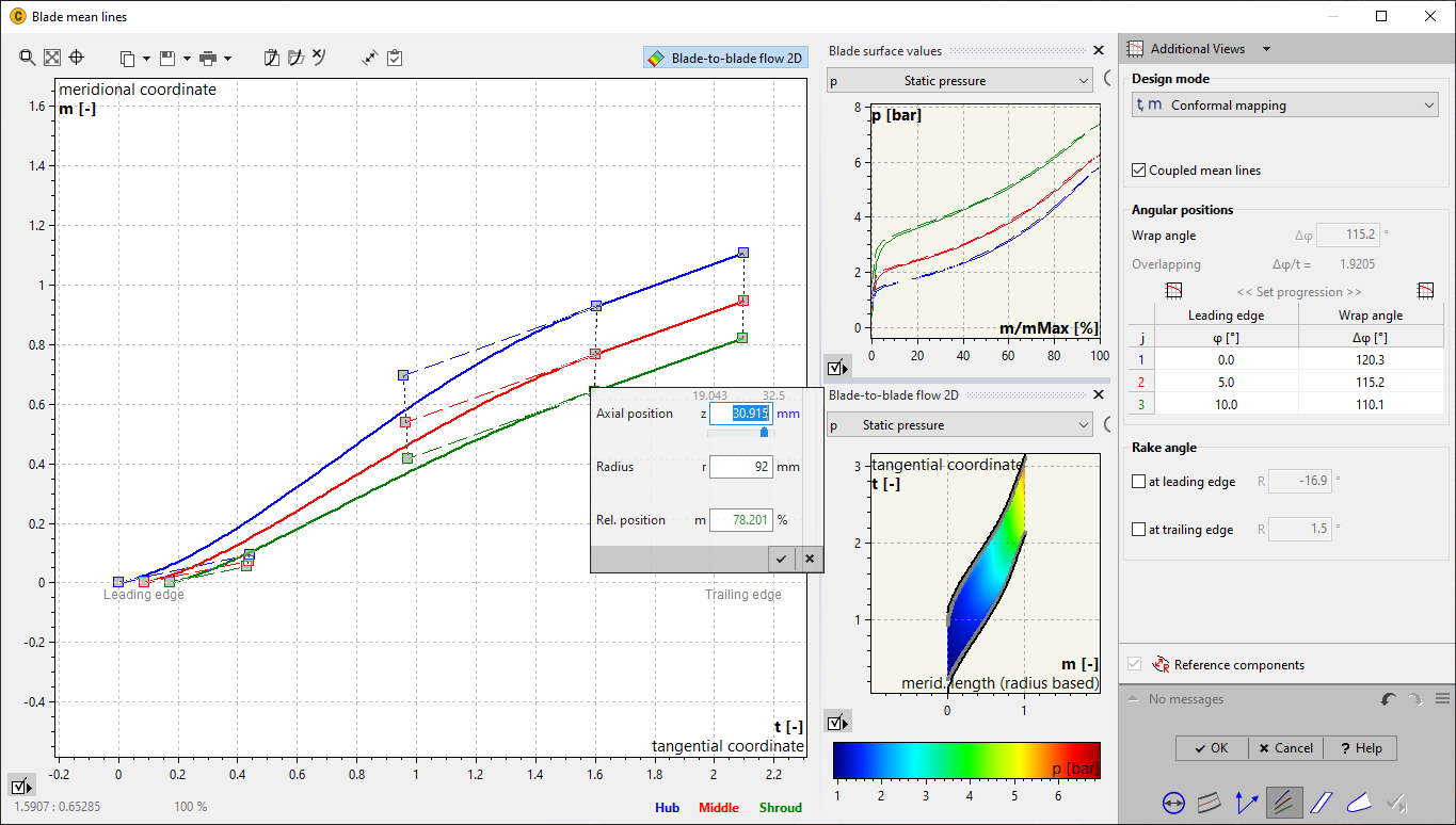
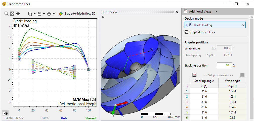
1D calculation blade-to-blade flow
Display of blade load during meanline design

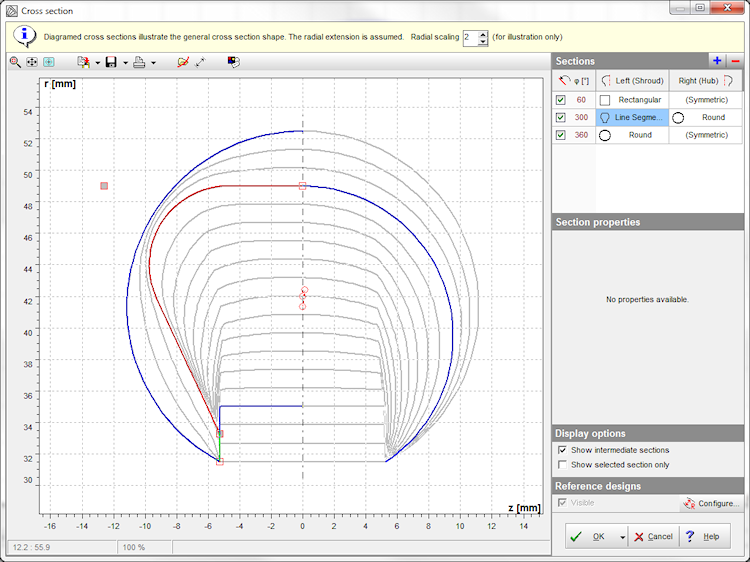
Elliptical cross-sections for volutes
Available for all round shapes
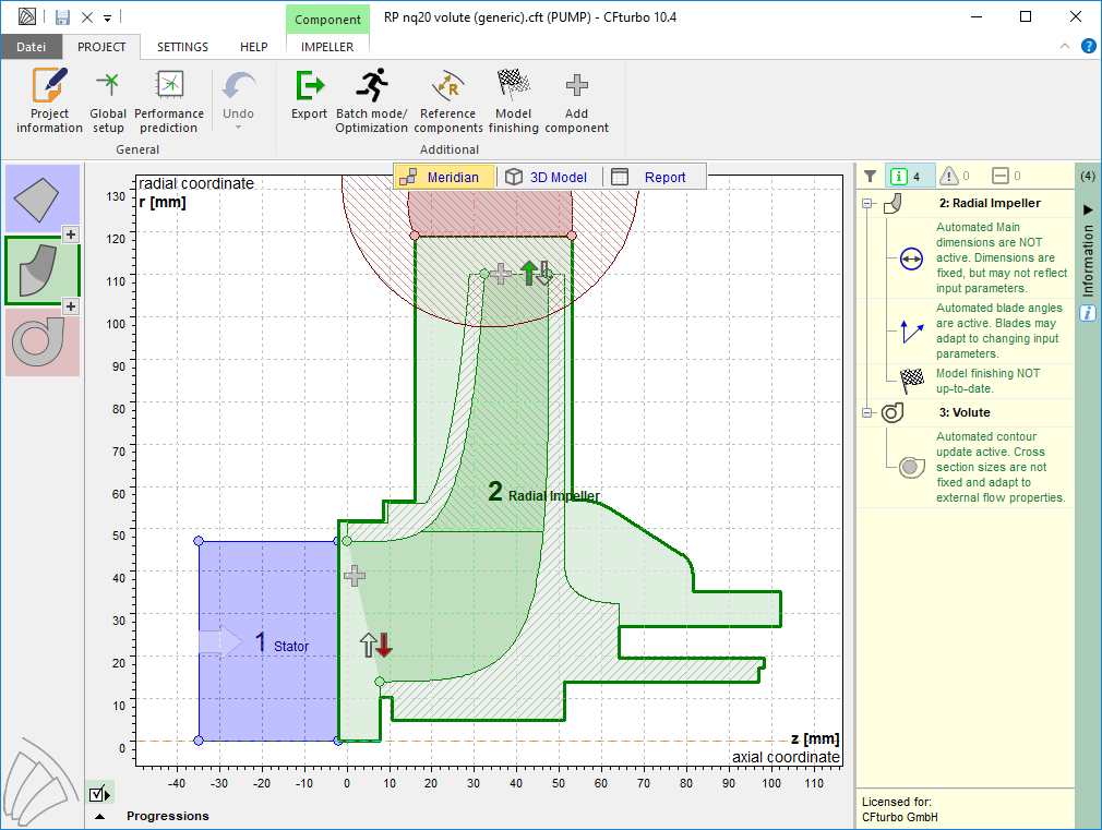
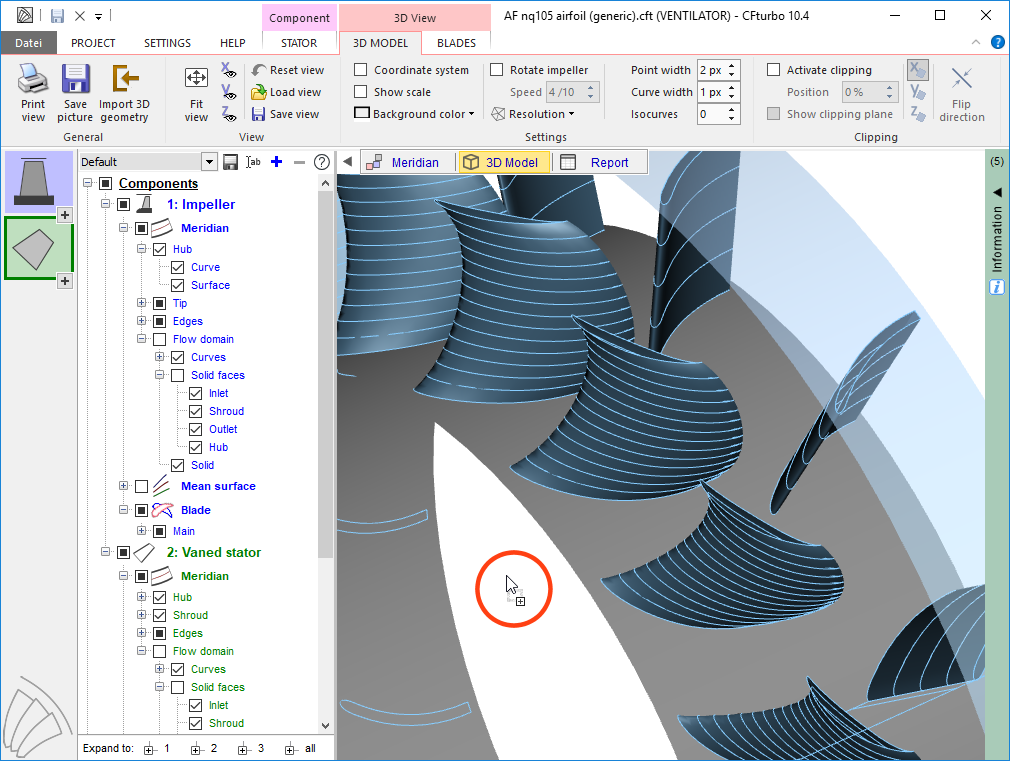
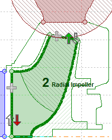
Meridional preview
Realistic meridional preview of the impeller within casing

3D model tree
Intuitive model tree with icons

Filtering messages
Filter between Information / Warning / Errors

CoolProp fluid property database
Direct access to the CoolProp library for real gas properties
CFturbo 10.3
Feburary 2018
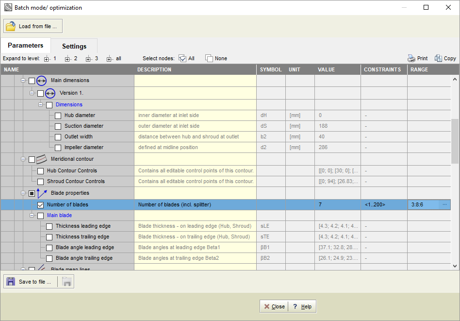
Batch mode / Optimization
Flexible configuration of all available parameters and export interfaces
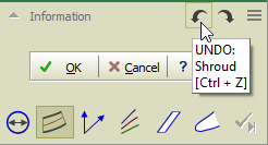
Undo / Redo
Available in all design step windows
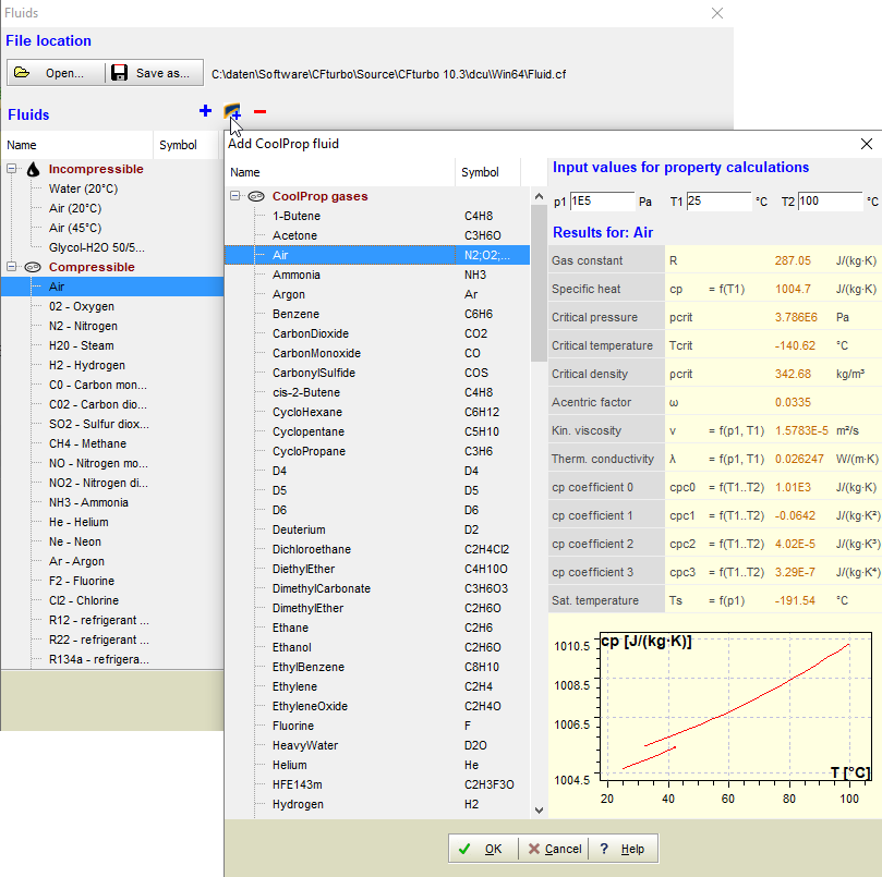
CoolProp Database
Library for fluid properties
www.coolprop.org

Gas mixtures
User-defined gas mixtures
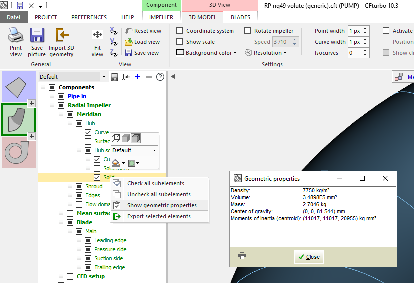
Display of solid state properties
Display of mass, mass center of gravity, and inertia for solid elements
Drag & Drop
For *.cft files in the CFturbo main window
3D properties
Adjust component color and translucency in the model tree
Secondary flow path
Design detailed hub and shroud contours as well as casing contour
Variable tip clearance
Linear transition between value at inlet and outlet
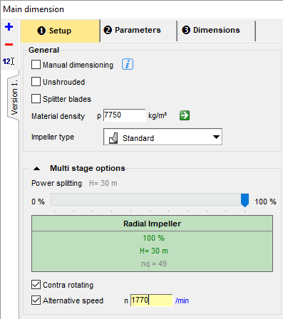
Variable rotational speed
- For multi-stage applications
- Varying speed for contra-rotating impellers
- Individual speed for each impeller

Second blade design mode
Airfoil design available in addition to meanline mode
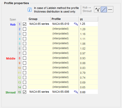
Multiple profile definitions
Define individual profiles on any blade section
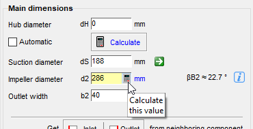
Main impeller dimensions
Optional individual calculation of impeller main dimensions
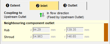
Independent rotor-stator interface
Rotor-stator interface (RSI) decoupled from geometry
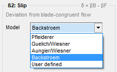
Additional slip factor model
Backstroem model now available
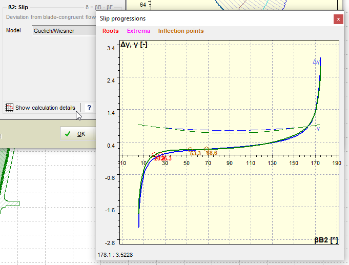
Slip factor calculation
Graphical information about slip factor calculation

Model finishing
- For the entire project
- Automatically on export
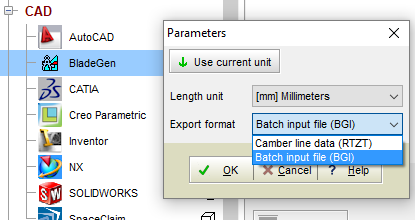
ANSYS export interface
New export interface to ANSYS BladeGen.bgi (additional to .rtzt)
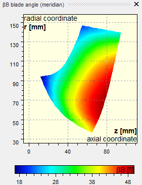
Additional diagrams for meanline design
- βB in meridian view
- Wrap angle
- Wrap angle in meridian view
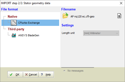
New import formats for 3D geometry data
- BladeGen and .cft format
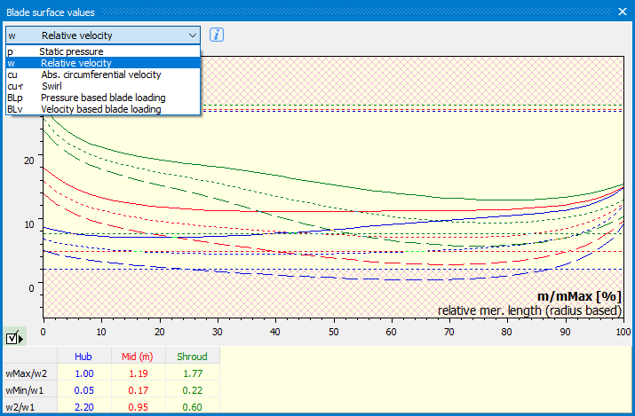
"Blade surface values." (Stanitz / Prian)
Now available in blade profiles dialogue and blade edge dialogue

Additional diagrams for stators, compressors, and turbines
- Isentropic Mach number
- Critical area
CFturbo 10.2
November 2016

Context menus
Menu pages become available depending on selected component and view
Use icons to navigate directly between design steps
Error information
In the design step windows
Windows Explorer Integration
Preview, properties page, additional columns, Windows search
Edge smoothing in the 3D view
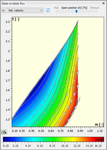
Blade-to-blade potential flow calculation
Show velocity and pressure distribution, absolute and relative velocity vectors
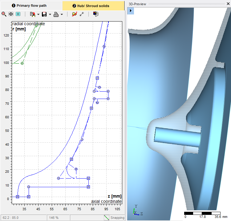
Solids for hub and shroud
- Solid model design of hub and shroud
- Available for CAD, CFD and FEA export
- Model finishing creates a material domain
Frontal view of blade geometry available in docking area
Parallel display of design diagram and frontal view

Automated update of main dimensions parameters, as an option
Use standard values, even after modification of the design point
New blade shapes for axial machines
Free-form blades and straight 2D blades
Flexible inlet conditions for volute design
Automated design or manual adjustment
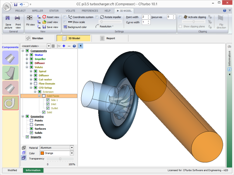
CFturbo 10.1
Feburary 2016

New export interface TCFD
OpenFOAM based CFD system for turbomachinery simulation

Preferences
All options in one window
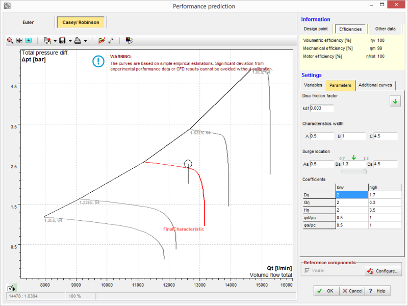
Performance map prediction for compressors
according to Casey/Robinson

Windows 10 support
supported operating systems are Windows 7, 8, 8.1, 10
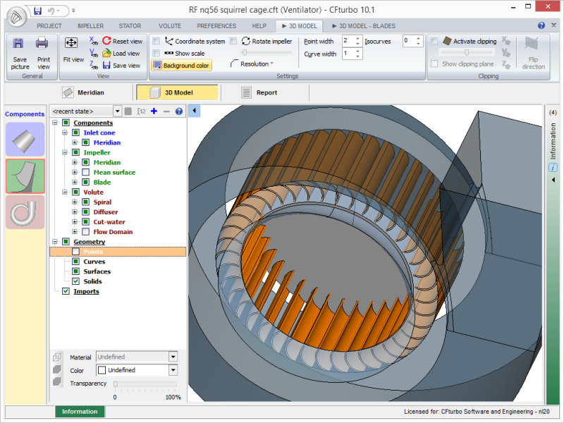
New impeller type "squirrel-cage" for centrifugal fans
specific design theory, empirical correlations and geometric properties

3 alternative blade thickness definitions
perpendicular to mean surface, perpendicular to mean line, tangential
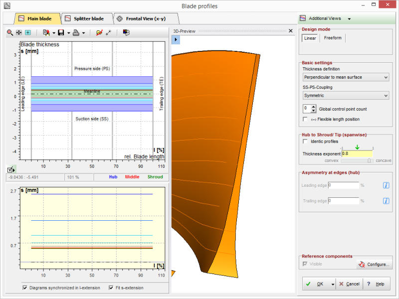
Blade thickness distribution from hub to shroud/tip
Thickness distribution along the blade height by an exponential function
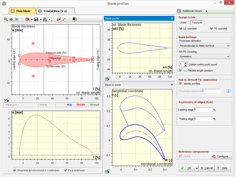
Alternative blade profiles
in absolute or relative coordinates within profile manager
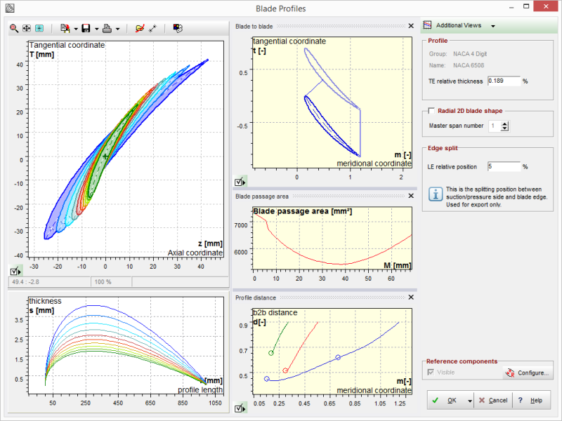
Additional diagrams for axial blades
Blade-to-blade, blade passage area, blade-to-blade distance

Blade thickness distribution in meridional view
for manufacturing
Additional region at diffuser outlet (inlet for turbines)
Downflow/inflow range for CFD
CFturbo 10.0
April 2015

64 bit version
alternative to the 32 bit version
Reference geometries in meridional view
for easier comparison of complete projects

2 impellers within one project
e.g. two-stage axial turbine or radial pump with inducer
Export of tetrahedral volume grids
for FEA or CFD

Axial pump design
specific design theory, empirical correlations and geometric properties

Axial fan design
specific design theory, empirical correlations and geometric properties
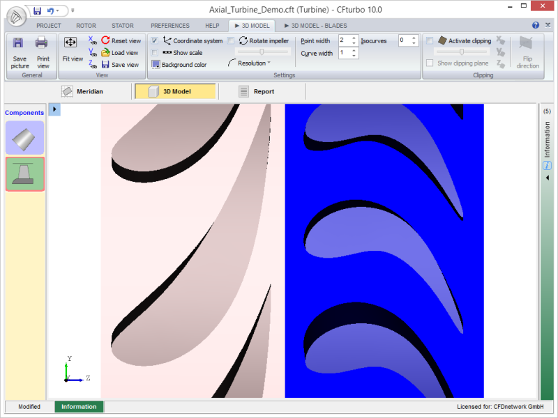
Axial turbine design
specific design theory, empirical correlations and geometric properties
Axial impeller/inducer design
specific design theory, empirical correlations and geometric properties
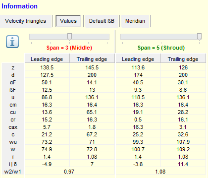
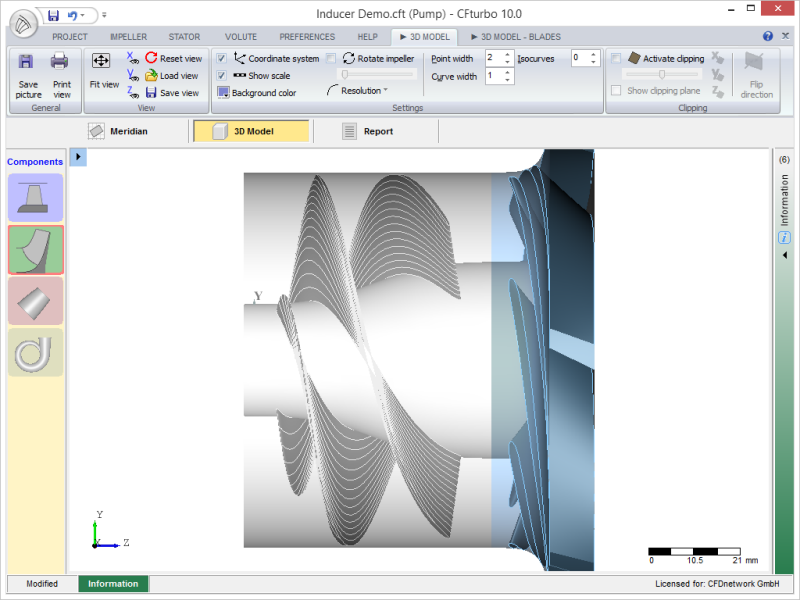
Show velocity triangles on a span
more information at blade design
Export interface to VistaTF
VistaTF enables quick recomputation of impellers at the design point
Import of meanlines
for reverse engineering
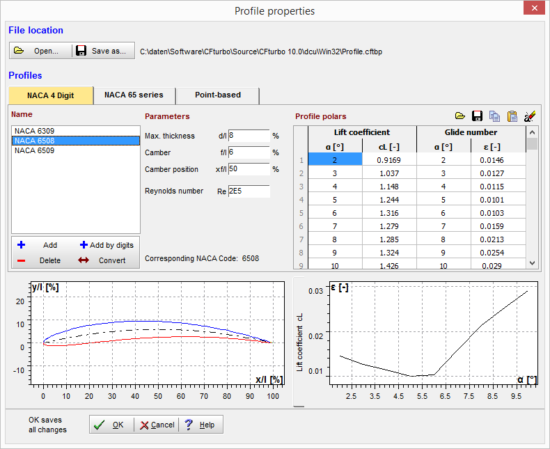
Use of NACA or point-based profiles
centralized data, extendable database
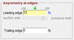
Asymmetrical blade profiles at leading and trailing edges
Definition of specific asymmetry at the blade edges
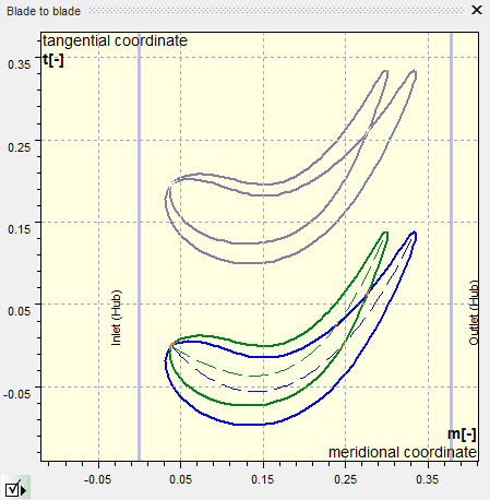
Blade-to-blade view
to show blade shape and curvature
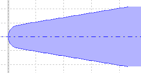
New leading edge type
with linear thickness change, nonsymmetry available
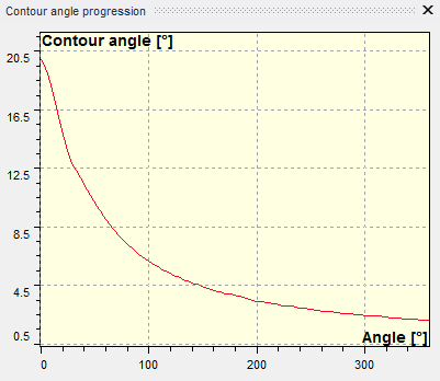
View slope angle
for better control of the spiral contour
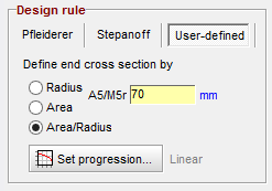
Specify A/r (area to radius) ratio
extended flexibility to control spiral contour
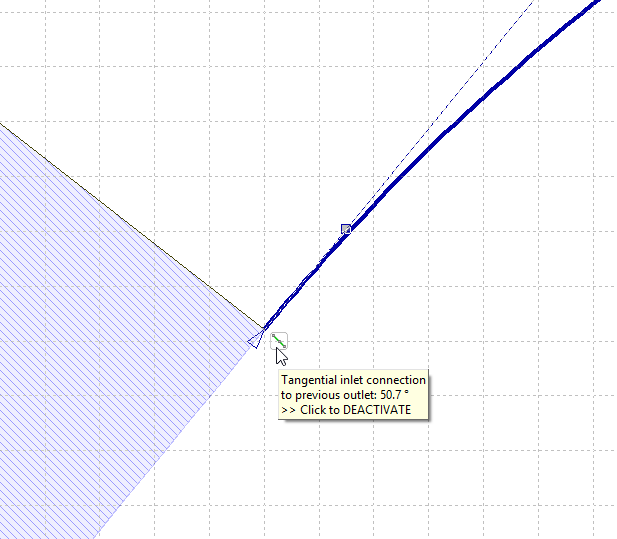
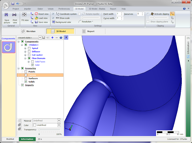
Tangential transition from spiral surface to discharge diffuser
3D model with enhanced surface
Spiral contour definition by circular arcs
e.g. create simple spiral shapes for fans
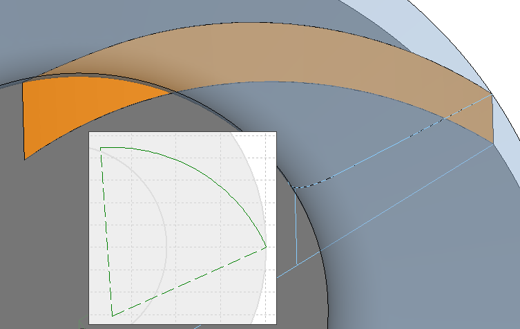
Double spiral splitter extension to the discharge diffuser
flexible positioning of the splitter extension
Fillets for double spiral splitter
Round up leading and trailing edge of the splitter
CFturbo 9.2
January 2014

Multiple definitions of specific speeds
to serve different geographical standards
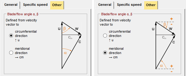
Flexible definition of flow and blade angles
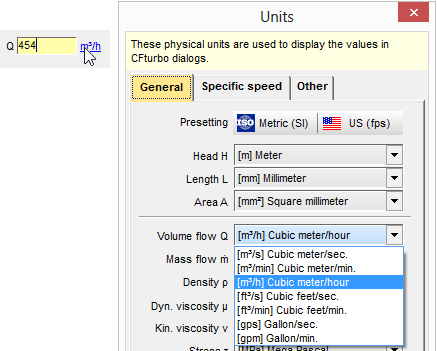
Convenient modification of units
Click on the unit of each input field to toggle and convert it.

Improved triangulation of 3D models
harmonic triangle distribution, adjustable triangulation parameters
Display options available in individual diagrams
both for main diagram and for history diagrams, displays assignment options
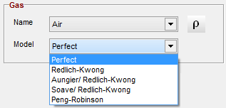
Real gas models
Various real gas models as an alternative to ideal gas approach
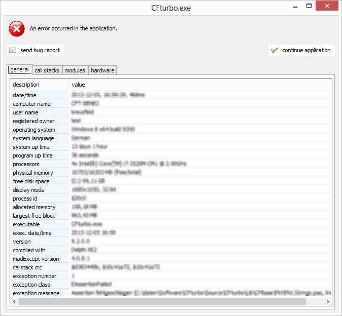
Improved error handling, including automated bug reports
Error descriptions with the possibility to send a bug report to CFturbo support
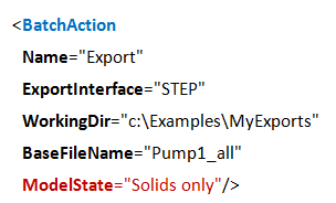
Load model state in batch mode
important for all surface/solid based export formats to define the specific geometry parts

Wastewater impeller design
specific design theory and empirical correlations
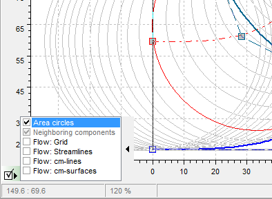
Show meridional contours with adjacent components
Optional display of neighboring components
Tangential transition in meridional view
Optional tangential coupling between individual curve elements and adjacent components
Display active empirical functions
to avoid design errors
Circular blade design
blades can be modelled as cylinder surfaces to support sheet metal design in 3D CAD
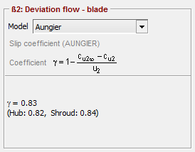
Slip factor correlation according to Aungier
Evolution of the Wiesner model
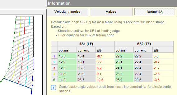
Display the optimum blade angle
including deviation compared to actual values; important to simple blade shapes
Basic functions for double spiral design
Splitter (2nd spiral cutwater) at variable position
Cutwater simple 3D trimming
alternative option to design the cutwater region
CFturbo 9.1
December 2012

New licensing software
Licenses are CFturbo module-based

Automatic update check
Time intervals can be configured
Flexible window setup
Add and remove diagrams based on personal preferences
3D preview in every design step
Including reference designs and imported geometries
Fast navigation to the next design step
without necessarily updating the 3D model
Finish component design automatically
Option in all design steps

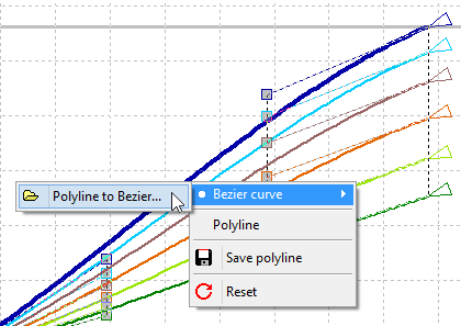
Approximation of polylines
Transformation of polylines to Bezier curves; can be used for switching between m, t-meanlines, and beta-profiles

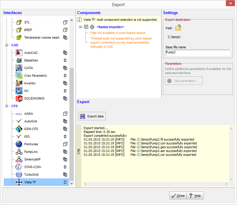
Export window
Select export format; create files for export or start your simulation
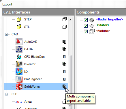
Export multiple components
Selected export interfaces enable joint export of multiple components
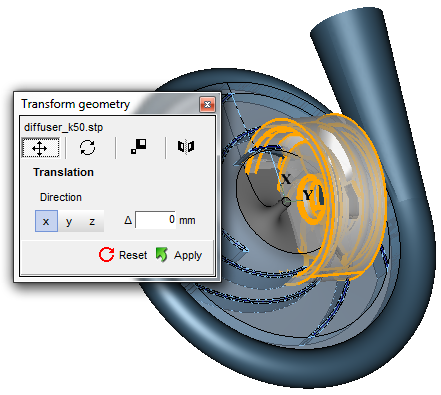
Transform imported 3D geometry
Translate, rotate, and scale imported models
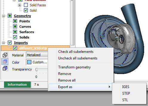
Export of imported and transformed 3D models
Save transformed import geometries as IGES, STEP or STL

Mouse configuration
Set up mouse buttons
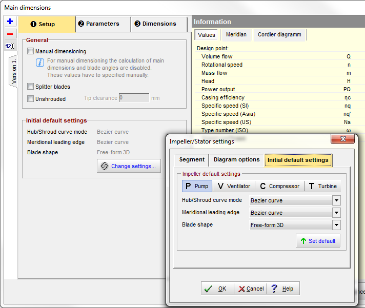
Define preferences
variable definition of preferences for meridian shape and blade type
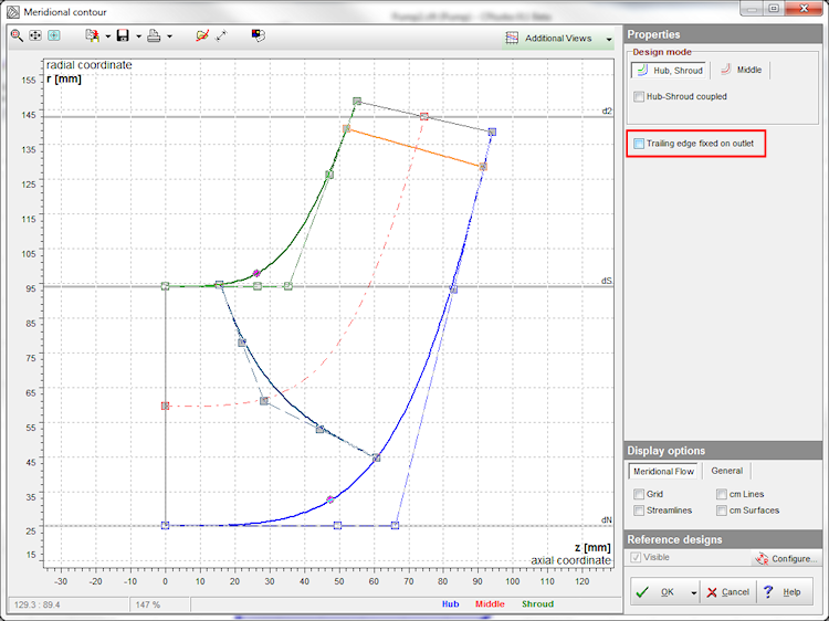
Position trailing edge in meridional view
As an option, decouple trailing edge at the end of the flow channel
Composite meridional contours
flexible design of hub and shroud consisting of several parts
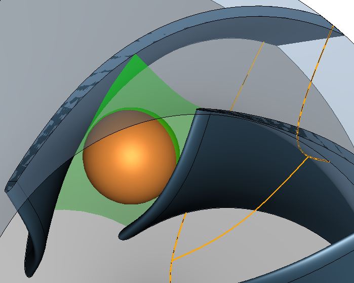
Compute throat area
Calculate throat area and the largest sphere diameter which can pass through the blade channel
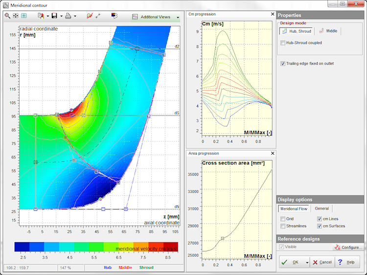
Potential flow calculation in meridional view
Calculation of the meridian flow according to a potential method
Calculate blade-to-blade flow
Calculate the blade load using Stanitz and Prian methodology
Create ruled surfaces
use two to 15 spans
Outlet width calculation
optional calculation of the outlet width b2 according to Stepanoff's theory using the help of ε2=cm2/√2gH

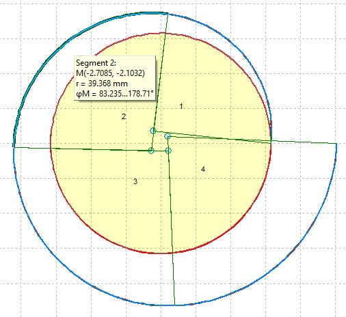
Arbitrary spiral cross-section
option to design left and right side independently
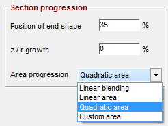
Variable cross-section designs in circumferential direction
optional definition of any number of cross-sections in circumferential direction
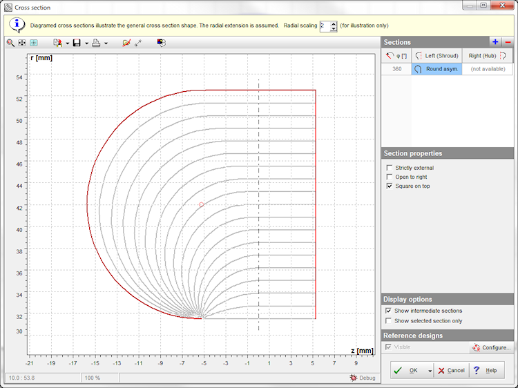
Asymmetric circular cross-section optional top square
for compact volute design
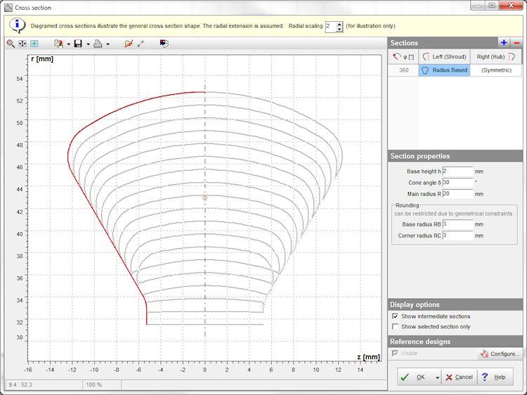
Cross section type "radius based"
Typical pump cross-section of straight lines and circular arcs
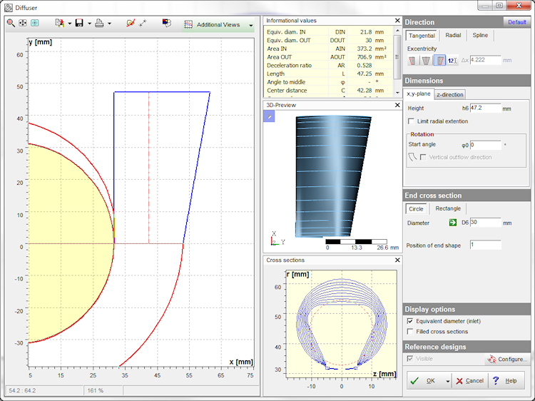
Discharge diffuser can be inclined
arbitrary inclination of the tangential diffuser
Cutwater fillet
now also available for asymmetric cross-sections
Spiral calculation
considers constraints of existing spiral geometries if required
CFturbo 9.0
June 2011
✔ Design of complete machines/stages consisting of multiple components
✔ Redesigned user interface of the main window
✔ New module "Vaned Stator" to design vaned and unvaned stators
✔ XML file format
✔ Viewer mode, if no license available
✔ Meanlines: design alternative by direct modification of the beta distribution
✔ Display all diagrams based on m, r or z
✔ Meridional view: coupling of Bezier points can be switched off
✔ Meridional view: Bezier point stop can be switched off
✔ Meridional view: axial positioning of the whole geometry
CFturbo 5 ... 8
2000 ... 2010
Kreila 1 ... 4
1985 - 2000
University of Technology Dresden