Impeller Design
Impellers and rotors are the heart of every turbomachine. Due to its high importance, we have invested many resources in this critical component.
Geometric flexibility and variety are essential to CFturbo's impeller design system.
Functions
- Wide range of specific speed Design different types of impellers in a specific speed range 8 < nq < 500 (EU), 400 < Ns < 25,000 (US)
- Shrouded and unshrouded impellers With manual positioning of the leading and trailing edges, splitter blades available
- Alternative design method for blades Besides standard meanline design, an airfoil design method is available for axial-type turbomachines
- Flexible meridional contours Complex shapes possible with control of geometric progressions
- Blade angle calculation Apply incident angles for leading edge design and choose between various slip factor correlations for trailing edge design
- Various blade shapes Blade shapes can be selected based on optimal fluid flow conditions, or on manufacturing constraints
- Flexible blade profiling Select and modify thickness distribution, or use predefined profiles
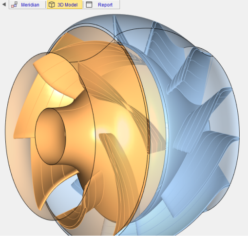
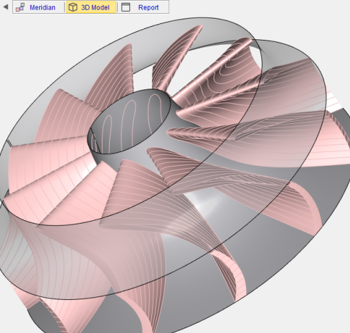
Design steps for radial and mixed-flow impellers
Applicable to pumps, fans, compressors and turbines
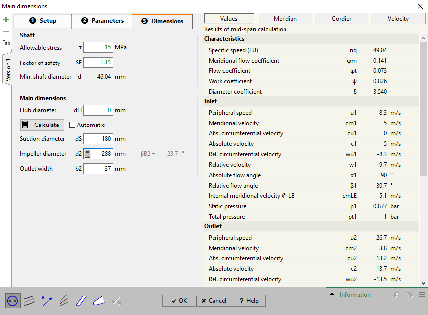
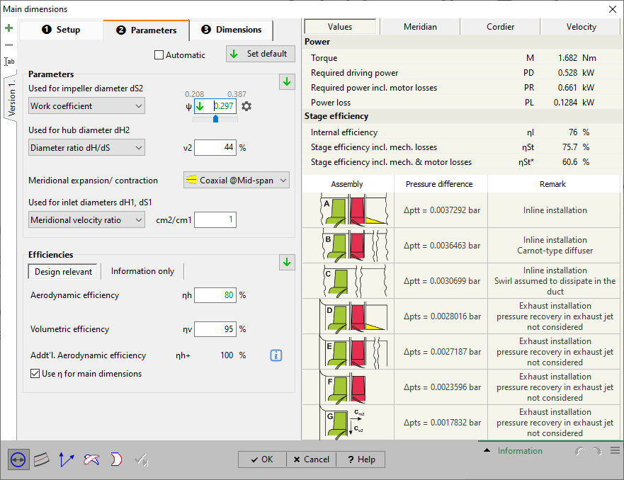
1. Main dimensions
- Calculation of the impeller main dimensions: hub diameter, suction diameter, outlet width, impeller diameter
- Application of internal or user-defined approximation functions to define impeller parameters
- 1D calculation for all important thermodynamic values
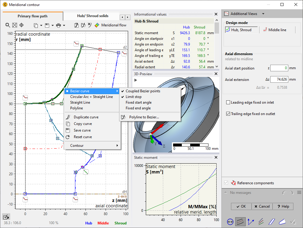
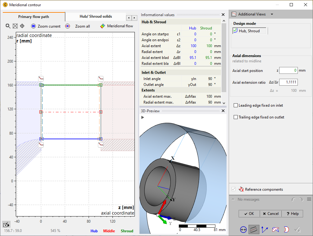
2. Meridional contour
- Design of the meridional contour using Bezier polynomials, lines and arcs or any polylines
- Positioning of straight or curved leading and trailing edges
- Display of various information about geometric parameters
- Calculation of the meridional flow based on potential flow method
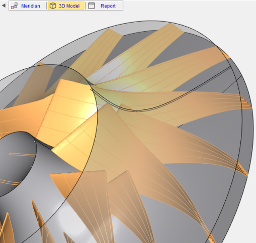
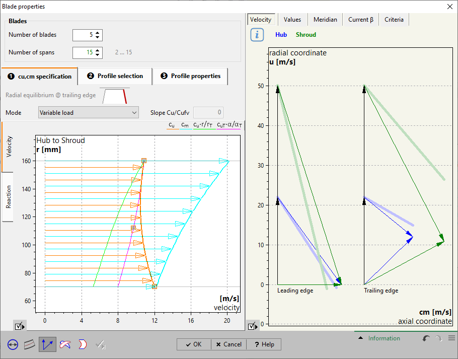
3. Blade properties
- Defining the blade shape: free-form 3D, free-form 2D, circular arc 2D, straight 2D, radial element blades, ruled surfaces
- Blade design on meridional flow surfaces (1 to 15 spans)
- Calculation of blade angles considering blade thickness and slip factor correlation
- View velocity triangles and see listing of velocity components and flow angles

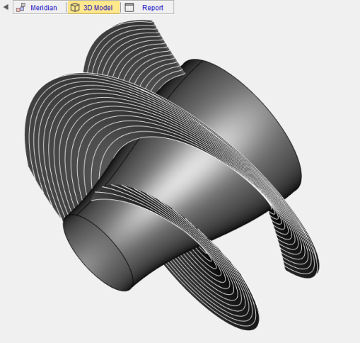
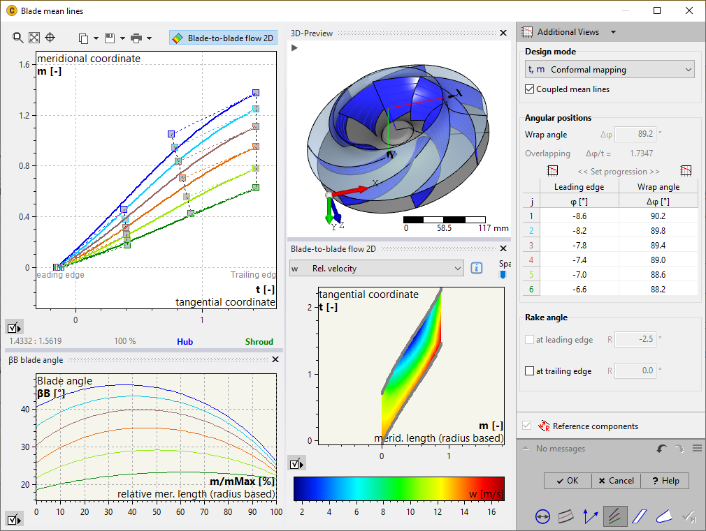
4. Blade mean lines
- Mean line definition on rotationally symmetric meridional flow surfaces. Use Bezier polynomials or arbitrary polylines. Conformal mapping to m-theta or m-beta
- Coupled or uncoupled blade mean lines
- Wrap angle definition or modification
- View of blade angle and cross-section profiles
- Calculation of velocity and pressure distributions in the blade channel
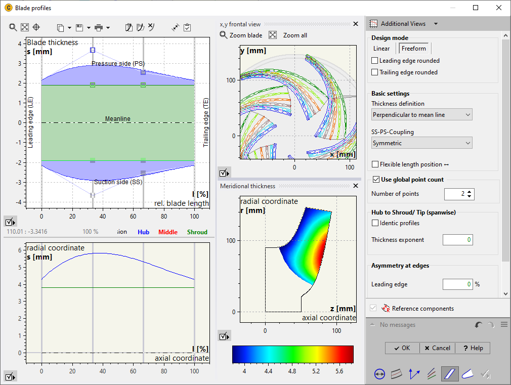
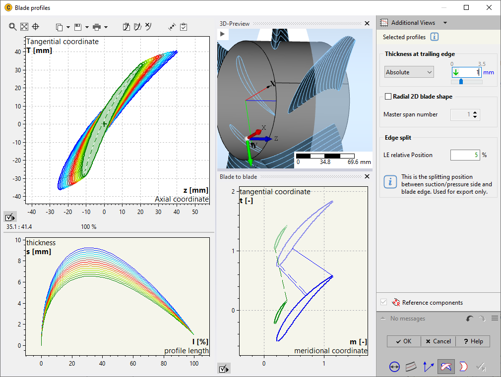
5. Blade profiles
- Definition of the blade thickness on the specific profile sections
- Linear thickness distribution, or free-form profiles with variable numbers of control points
- Optional use of predefined profiles
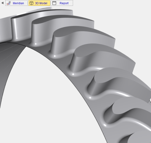
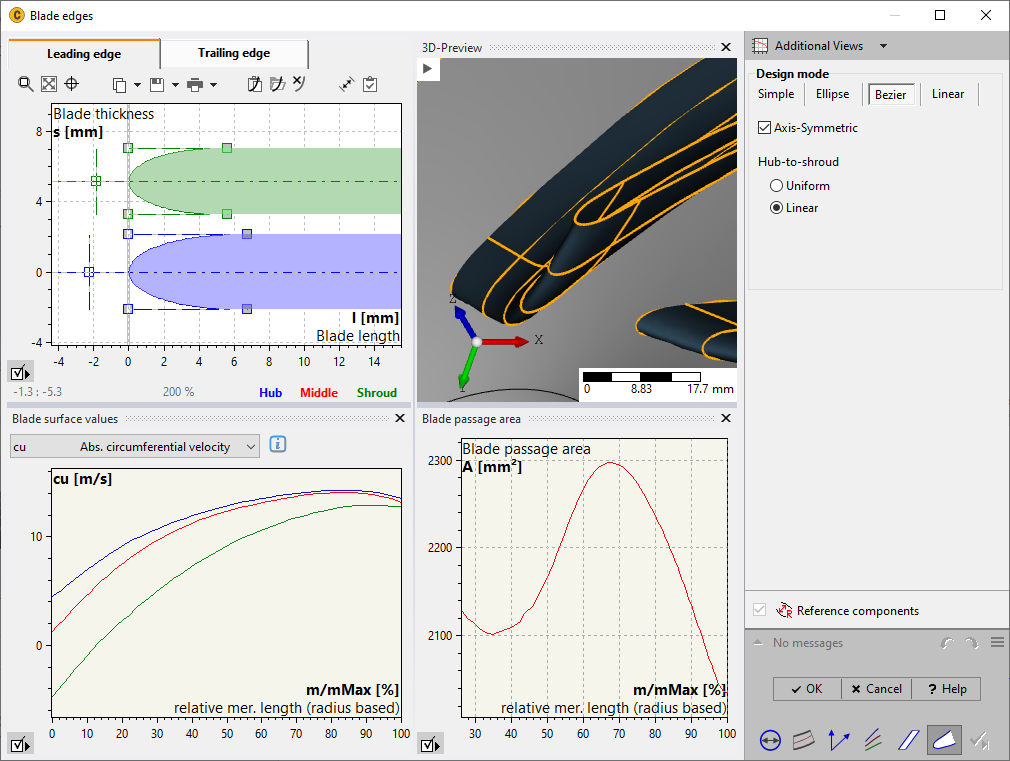
6. Blade edges
- Rounding of the leading and / or trailing edges using Bezier polynomials, ellipses, linear shapes or cutoffs
- Symmetrical and asymmetrical shapes
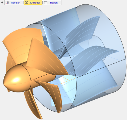
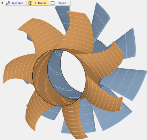
Axial Impeller Design
Applicable to pumps, fans, compressors and turbines
1. Main dimensions
- Calculation of the impeller main dimensions of the impeller: hub and tip diameter at inlet and outlet
- Application of internal or user-defined approximation functions for defining impeller parameters
- Two alternative design modes: airfoil / hydrofoil design or mean line design
2. Meridional contour
- Design of the meridional contour using Bezier polynomials, lines and arcs or any polylines
- Positioning of the maximum blade extension
- View various information about main geometric parameters
- Calculation of the meridional flow based on potential flow method
3. Blade properties
- Blade design on meridional flow surfaces (1 to 15 spans)
- Modify the cu, cm distribution
- Select profiles and angle of attack
- Calculate stagger angles and chord length
- View velocity triangles and see listing of velocity components and flow angles
4. Blade profiles
- View blade profiles
- See thickness distribution
- Apply radial 2D blade shapes if required
5. Blade sweep
- 3D blade sweep in two alternative modes
- Profile threading either in the center of gravity or at the front or rear edge
- Axial positioning of the blade

Impeller design made easy
Register and download CFturbo software for a free trial today.